Standards Compliance
5
5.3 UL Standards
YASKAWA SIEPC71061753C GA500 Technical Manual 189
Comply with local standards for correct wire gauges in the region where you will use the drive.
WARNING! Electrical Shock Hazard. Only connect factory-recommended devices or circuits to drive terminals B1, B2, -, +1,
and +2. Do not connect AC power to these terminals. Incorrect wiring can cause damage to the drive and serious injury or death
from fire.
Note:
• The recommended wire gauges are based on drive continuous current ratings with 75 °C (167 °F) 600 V class 2 heat-resistant indoor
PVC wire. Assume these conditions:
–Ambient temperature: 40 °C (104 °F) maximum
–Wiring distance: 100 m (3281 ft) maximum
–Normal Duty rated current value
• Refer to the instruction manual for each device for recommended wire gauges to connect peripheral devices or options to terminals +1,
+2, -, B1, and B2. Contact Yaskawa or your nearest sales representative if the recommended wire gauges for the peripheral devices or
options are out of the range of the applicable gauges for the drive.
• When you use crimp ferrules on the wire ends, contact Yaskawa or your nearest sales representative.
Wire Selection Precautions
Think about line voltage drop before selecting wire gauges. Select wire gauges that drop the voltage by 2% or less
of the rated voltage. Increase the wire gauge and the cable length when the risk of voltage drops increases.
Calculate line voltage drop with this formula:
Line voltage drop (V) = × wire resistance (Ω/km) × wiring distance (m) × motor rated current (A) × 10
-3
.
Precautions during Wiring
• Refer to “Yaskawa AC Drive Option Braking Unit, Braking Resistor Unit Instruction Manual
(TOBPC72060001)” for information about wire gauges and tightening torques to connect braking resistor units.
• Use terminals +1 and - to connect a regenerative converter or regenerative unit.
WARNING! Fire Hazard. Do not connect a braking resistor to terminals +1 or -. Use terminals B1 and B2 for the braking resistor
connections. If you connect a braking resistor to the incorrect terminals, it can cause damage to the drive and braking circuit and
serious injury or death.
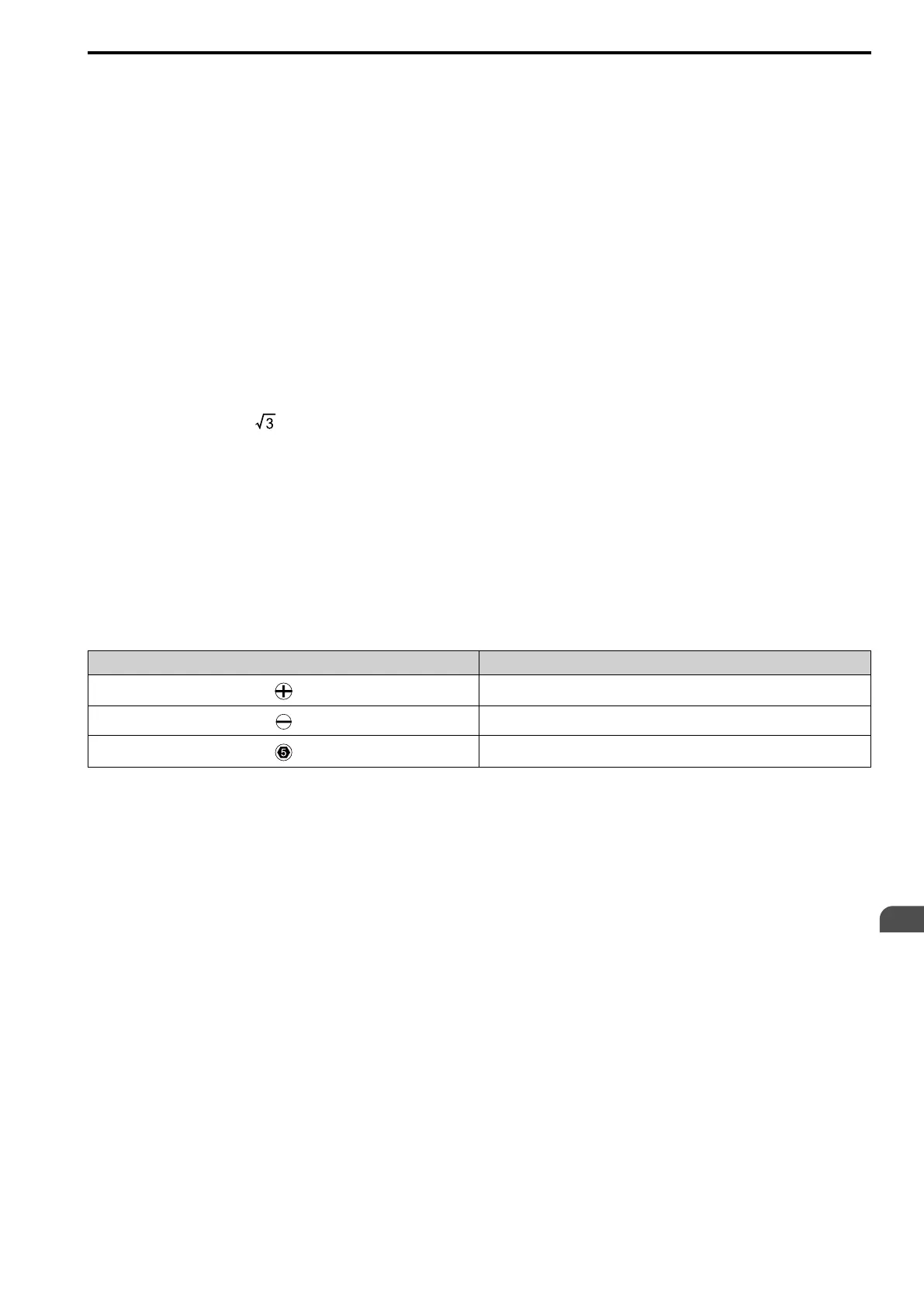
Screw Shape
These tables use icons in Table 5.17 to show the shapes of the screw heads.
Table 5.17 Icons to Identify Screw Shapes
Icon Screw Shape
+/-
Slotted (-)
Hex socket cap (WAF: 5 mm)

 Loading...


