5.3 UL Standards
188 YASKAWA SIEPC71061753C GA500 Technical Manual
Figure 5.15 Permitted Angle
• Put the bit all the way into the hex socket to tighten the hex socket cap screw.
• When you tighten slotted screws, hold the straight-edge screwdriver perpendicularly to the screw. Make sure
that you align the end of the straight-edge screwdriver with the screw groove.
Figure 5.16 Tightening Slotted Screws
• After you connect the wires to the terminal block, lightly pull on the wires to make sure that they do not come
out of the terminals.
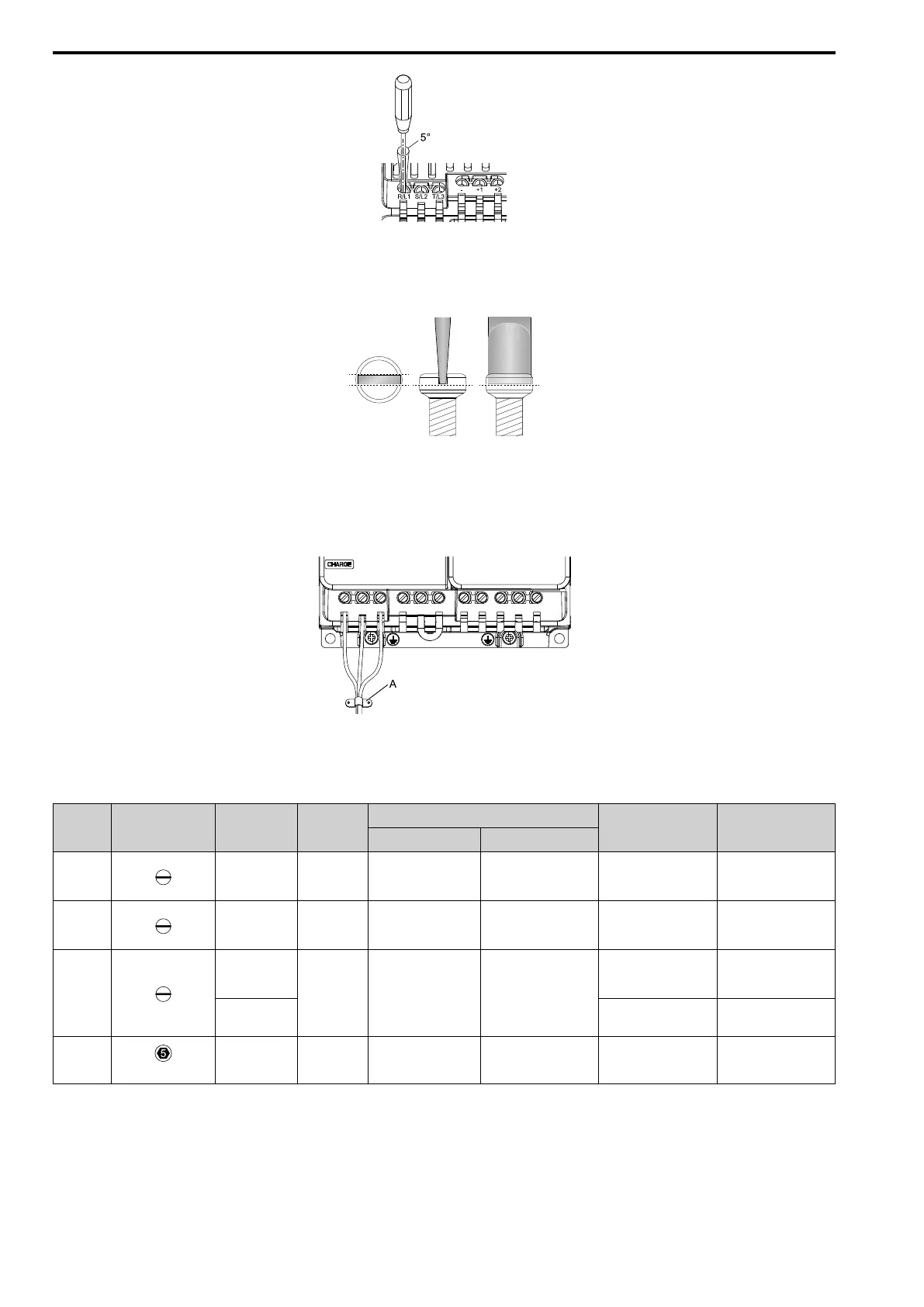
• Do not let strain on the wiring cause damage. Use a strain relief near the wiring to release the tension. Refer to
Figure 5.17 for an example.
A - Cable clamp
Figure 5.17 Strain Relief Example
Table 5.16 Recommended Wiring Tools
Screw
Size
Screw Shape Wire Gauge Adapter
Bit
Torque Driver Model
(Tightening Torque)
Torque Wrench
(Tightening Torque)
Model Manufacturer
M3 - Bit SF-BIT-SL 0,5X3,0-70 PHOENIX CONTACT
TSD-M 1,2NM
(0.3 - 1.2 N∙m
(2.7 - 10.6 lbf∙in))
-
M4 - Bit SF-BIT-SL 1,0X4,0-70 PHOENIX CONTACT
TSD-M 3NM
(1.2 - 3.0 N∙m
(10.6 - 26.6 lbf∙in))
-
M5
*1
≤ 25 mm
2
(AWG 10)
Bit SF-BIT-SL 1,2X6,5-70 PHOENIX CONTACT
TSD-M 3NM
(1.2 - 3.0 N∙m
(10.6 - 26.6 lbf∙in))
-
≥ 30 mm
2
(AWG 8)
-
4.1 - 4.5 N∙m
(36.3 - 39.8 lbf∙in)
*2 *3
M6
(WAF: 5 mm)
- Bit SF-BIT-HEX 5-50 PHOENIX CONTACT -
5 - 9 N∙m
(44.3 - 79.7 lbf∙in)
*2 *3
*1 When you wire drive models 2042, 2056, 4031, 4038, 4044, and 4060, select the correct tools for the wire gauge.
*2 Use 6.35 mm (0.25 in) bit socket holder.
*3 Use a torque wrench that can apply this torque measurement range.
■ Main Circuit Wire Gauges and Tightening Torques
Refer to Single-Phase 200 V Class on page 190, Three-Phase 200 V Class on page 191, and Three-Phase 400 V
Class on page 194 for the recommended wire gauges and tightening torques of the main circuit terminals.

 Loading...


