3.2 Operating Procedures for Utility Functions
3.2.28 Advanced Autotuning without Reference (Fn201)
3-73
3-3
Type
Select the type according to the machine element to drive. If there is
noise or if the gain does not increase, better results may be obtained by
changing the rigidity type. Select the type according to the following
guidelines.
1: Belt drive mechanisms
2: Ball screw drive mechanisms (default setting)
3: Rigid systems in which the Servomotor is directly coupled to the
machine (without gear or other drive system)
3-4
Stroke (Travel Distance)
Set the travel distance.
• Travel distance setting range: -99,990,000 to 99,990,000 reference
units
• Minimum setting increment: 1,000 reference units
•
The negative direction is for reverse rotation, and the positive direction is
for forward rotation. The travel distance from the current position is given.
• Default setting: Approx. 3 rotations
If the Servomotor’s encoder resolution is 16,777,216 (24 bits), the
stroke (travel distance) will be set to 800,000. If the default electronic
gear ratio is used (Pn20E = 64 and Pn210 = 1), then
Note: 1. Set the parameters so that the number of motor rotations is at least 0.5.
Otherwise, ERROR will be displayed and advanced autotuning will not be
possible.
2. To calculate the moment of inertia and ensure precise tuning, we recom-
mend that you set the number of motor rotations to approximately 3.
3. For an SGMCS or SGMCV Direct Drive Servomotor, the default setting for
the number of motor rotations is approximately 0.3.
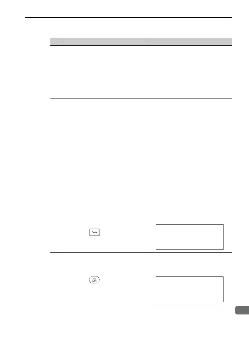
4
Press the Key.
The execution display for advanced
autotuning will appear.
5
Press the Key.
The servo will be turned ON and the
display will change from
BB
to
RUN
.
Note: If the mode is set to 2 or 3, Pn141
will be displayed instead of Pn102.
Continued on next page.
Continued from previous page.
Step Operation Result
×
800,000
16,777,216
64
1
≈ 3 (revolutions)
1:BB AAT
Pn103 =00000
Pn100=0040.0
Pn101=0020.00
Pn102=0040.0
1:RUN AAT
Pn103 =00000
Pn100=0040.0
Pn101=0020.00
Pn141=0050.0

 Loading...


