Parameter Details
5
5.2 b: Application
YASKAWA SIEPYAIH6B01A HV600 AC Drive Bypass Technical Reference 213
Note:
When you change b5-38 and b5-46, the drive will not automatically convert the parameters in Table 5.26.
For example, when you set YA-01 = 70.0 [PSI] and change these parameters:
• b5-46 from 1 [PSI] to 8 [Bar]
• b5-38 from 145.0 to 10.0
The drive changes only the unit setting and YA-01 will be 70.0 [Bar]. When the setpoint value after you change b5-38 and b5-46 is more than
b5-38, the drive internally limits the setpoint value to 200% of b5-38. The drive regards the YA-01 setting as 20.0 [Bar].
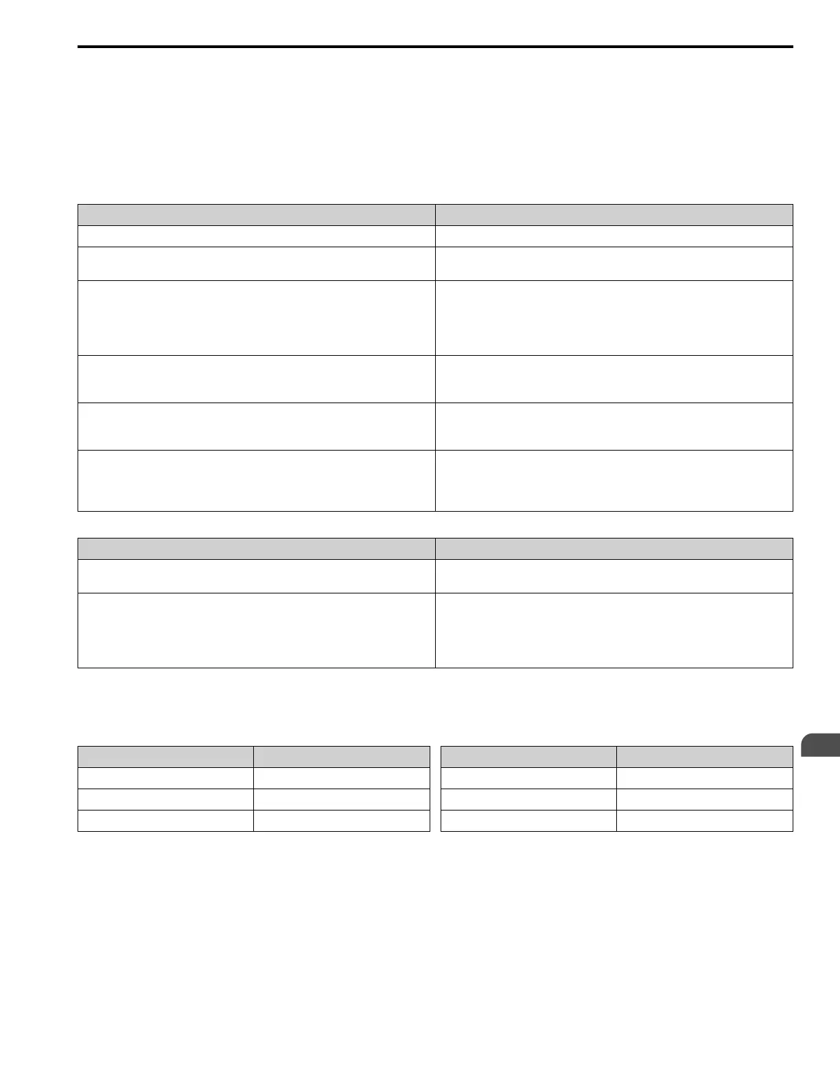
Table 5.26 Parameters Set by b5-38 and b5-46
Parameter Groups No.
b5 b5-71 [Min PID Transducer Scaling]
S5 • S5-06 [HAND Setpoint]
• S5-12 [HAND Setpoint 2]
Y1 • Y1-04 [Sleep Wake-up Level]
• Y1-08 [Low Feedback Level]
• Y1-11 [High Feedback Level]
• Y1-14 [High Feedback Hysteresis Level]
• Y1-15 [Maximum Setpoint Difference]
Y2 • Y2-05 [Sleep Boost Level]
• Y2-08 [Delta Feedback Drop Level]
• Y2-25 [Anti-No-Flow Release Level]
Y4 • Y4-01 [Pre-Charge Level]
• Y4-18 [Differential Level]
• Y4-37 [Pressure Reached Hysteresis Lvl]
YA • YA-01 [Setpoint 1]
• YA-02 [Setpoint 2]
• YA-03 [Setpoint 3]
• YA-04 [Setpoint 4]
Table 5.27 Monitors Set by b5-38 and b5-46
Monitor Groups No.
U1 • U1-60 [System Setpoint]
• U1-61 [System Feedback]
U5 • U5-01 [PID Feedback]
• U5-04 [PID Setpoint]
• U5-79 [PI Feedback Backup]
• U5-81 [Differential PI Fdbk]
• U5-99 [PID Setpoint Command]
Full-Scale of the PID Analog Input Signals
The full-scale of the analog signals listed in this table go from b5-71 [Min PID Transducer Scaling] to b5-38 [PID
User Unit Display Scaling].
H3-xx Setting MFAI
B PID Feedback
C PID Setpoint
24 PID Feedback Backup
H3-xx Setting MFAI
2B Emergency Override PID Feedback
2D Differential Level Source
2E HAND Frequency Ref or Setpoint
*1
*1 Only when b5-01 = 1 [PID Mode Setting = Standard] and S5-03 = 1 [HAND Mode PID Selection = Enabled]
Note:
When you set b5-71 < 0, the drive appropriately scales the setpoint and feedback values of the drive, but internally limits to 0 when the
reported value from the transducer is negative.
Custom Units
These selections are available for custom system units:

 Loading...


