EasyManuals Logo

YASKAWA HV600 User Manual

YASKAWA HV600
794 pages
To Next Page IconTo Next Page
To Previous Page IconTo Previous Page
Page #551 background imageLoading...
Page #551 background image
Specifications
7
7.10 Peripheral Devices and Options
YASKAWA SIEPYAIH6B01A HV600 AC Drive Bypass Technical Reference 551
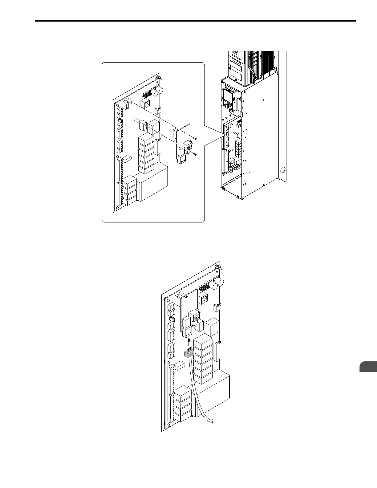
3. Use the two screws included in the option kit to fasten the option card to the metal standoffs on the bypass
PCB. Use a short-shaft, magnetic screwdriver for narrow enclosure models H6BPxxxx. Tighten each screw to
0.5 to 0.6 N•m (4.4 to 5.3 in lbs).
Figure 7.6 Insert Option into Bypass PCB CN5 Connector Port
4. Firmly insert the end of the customer-supplied network cable into the CN1 connection port on the option
board. When you have a dual-port option, connect two network cables to the two network ports in CN1 for
flexibility in cabling topology.
Figure 7.7 Connect Network Cable to Option (SI-W3 LonWorks Example)
CN5

Table of Contents

Other manuals for YASKAWA HV600

Questions and Answers:

Question and Answer IconNeed help?

Do you have a question about the YASKAWA HV600 and is the answer not in the manual?

YASKAWA HV600 Specifications

General IconGeneral
CategoryDC Drives
SeriesHV600
Overload Capacity150% for 60 seconds
Output Voltage0 - Input Voltage
EnclosureNEMA 1, NEMA 12
CommunicationEthernet/IP, Modbus, DeviceNet, Profibus
SafetySafe Torque Off (STO)
Protection FeaturesOvercurrent, Overvoltage, Undervoltage, Short Circuit
Humidity5-95% (non-condensing)
AltitudeUp to 1000m (3280ft) without derating
Control MethodVector Control

Related product manuals