8.3 Maintenance
560 YASKAWA SIEPYAIH6B01A HV600 AC Drive Bypass Technical Reference
When the monitor value is 100%, the component is at the end of its useful life and there is an increased risk of drive
malfunction. Yaskawa recommends that you check the maintenance period regularly to make sure that you get the
maximum performance life.
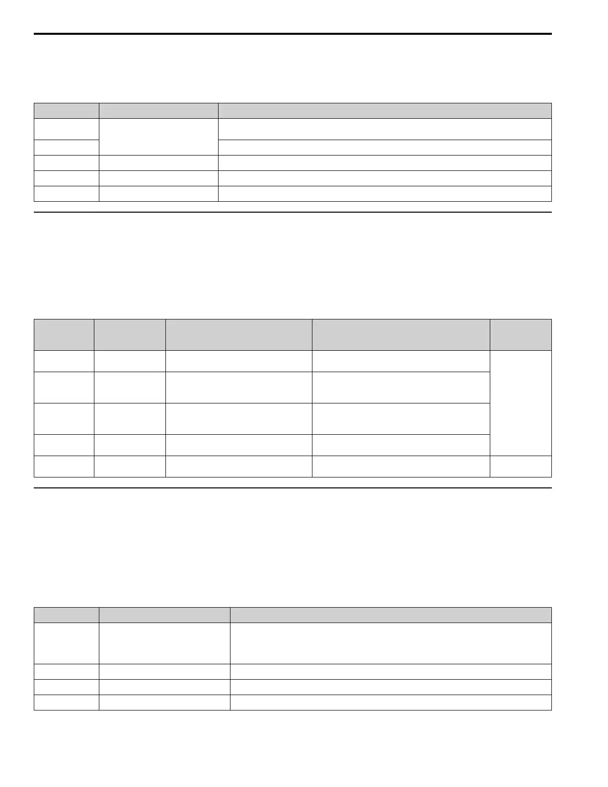
Table 8.8 Performance Life Monitors
Monitor No. Parts Description
U4-03
Cooling fan
Shows the total operation time of fans as 0 to 99999 hours. After this value is 99999, the drive automatically resets it
to 0.
U4-04
Shows the total fan operation time as a percentage of the specified maintenance period.
U4-05 Electrolytic capacitor
Shows the total capacitor usage time as a percentage of the specified maintenance period.
U4-06 Soft charge bypass relay
Shows the number of times the drive is energized as a percentage of the performance life of the inrush circuit.
U4-07 IGBT
Shows the percentage of the maintenance period reached by the IGBTs.
◆ Alarm Outputs for Maintenance Monitors
You can use H2-xx [Multi-Function Digital Out] to send a message that tells you when a specified component is near
the end of its performance life estimate. Set H2-xx to the applicable value for your component as shown in Table 8.9.
When the specified component is near the end of its performance life estimate, the MFDO terminals set for H2-xx =
2F [Maintenance Notification] will turn ON, and the keypad will show an alarm that identifies the component to
replace.
Table 8.9 Maintenance Period Alarms
Display Alarm Name Cause Possible Solutions
Digital Outputs
(Setting Value in
H2-xx)
LT-1
Cooling Fan
Maintenance Time
The cooling fan is at 90% of its expected
performance life.
Replace the cooling fan, then set o4-03 = 0 [Fan Operation
Time Setting = 0 h] to reset the cooling fan operation time.
2F
LT-2
Capacitor Maintenance
Time
The capacitors for the main circuit and control
circuit are at 90% of expected performance life.
Replace the board or the drive.
Contact Yaskawa or your nearest sales representative to
replace the board.
LT-3
SoftChargeBypassRe
lay MainteTime
The soft charge bypass relay is at 90% of its
performance life estimate.
Replace the board or the drive.
Contact Yaskawa or your nearest sales representative to
replace the board.
LT-4
IGBT Maintenance
Time (50%)
The IGBT is at 50% of its expected performance
life.
Check the load, carrier frequency, and output frequency.
TrPC
IGBT Maintenance
Time (90%)
The IGBT is at 90% of its expected performance
life.
Replace the IGBT or the drive.
10
◆ Related Parameters
Replace the component, then set o4-03, o4-05, o4-07, and o4-09 [Maintenance Setting] = 0 to reset the Maintenance
Monitor. If you do not reset these parameters after you replace the parts, the Maintenance Monitor function will
continue to count down the performance life from the value from the previous part. If you do not reset the
Maintenance Monitor, the drive will not have the correct value of the performance life for the new part.
Note:
The maintenance period is different for different operating environments.
Table 8.10 Maintenance Setting Parameters
No. Name Function
o4-03 Fan Operation Time Setting Sets the value from which to start the cumulative drive cooling fan operation time in 10-hour units.
Note:
When o4-03 = 30 has been set, the drive will count the operation time for the cooling fan from 300 hours and
U4-03 [Cooling Fan Ope Time] will show 300 h.
o4-05
Capacitor Maintenance Setting Sets the value from which to start the count for the main circuit capacitor maintenance period as a percentage.
o4-07 Softcharge Relay Maintenance Set Sets as a percentage the value from which to start the count for the soft charge bypass relay maintenance time.
o4-09 IGBT Maintenance Setting Sets the value from which to start the count for the IGBT maintenance period as a percentage.
 Loading...


