10.6 MEMOBUS/Modbus Communications
748 YASKAWA SIEPYAIH6B01A HV600 AC Drive Bypass Technical Reference
■ Writing to Non-Consecutive Holding Registers
The bypass uses function code 67 (Hex.) and subfunction code 010E (Hex.) to read data with a maximum of 60
holding registers.
You must give the holding register number from which to write separately.
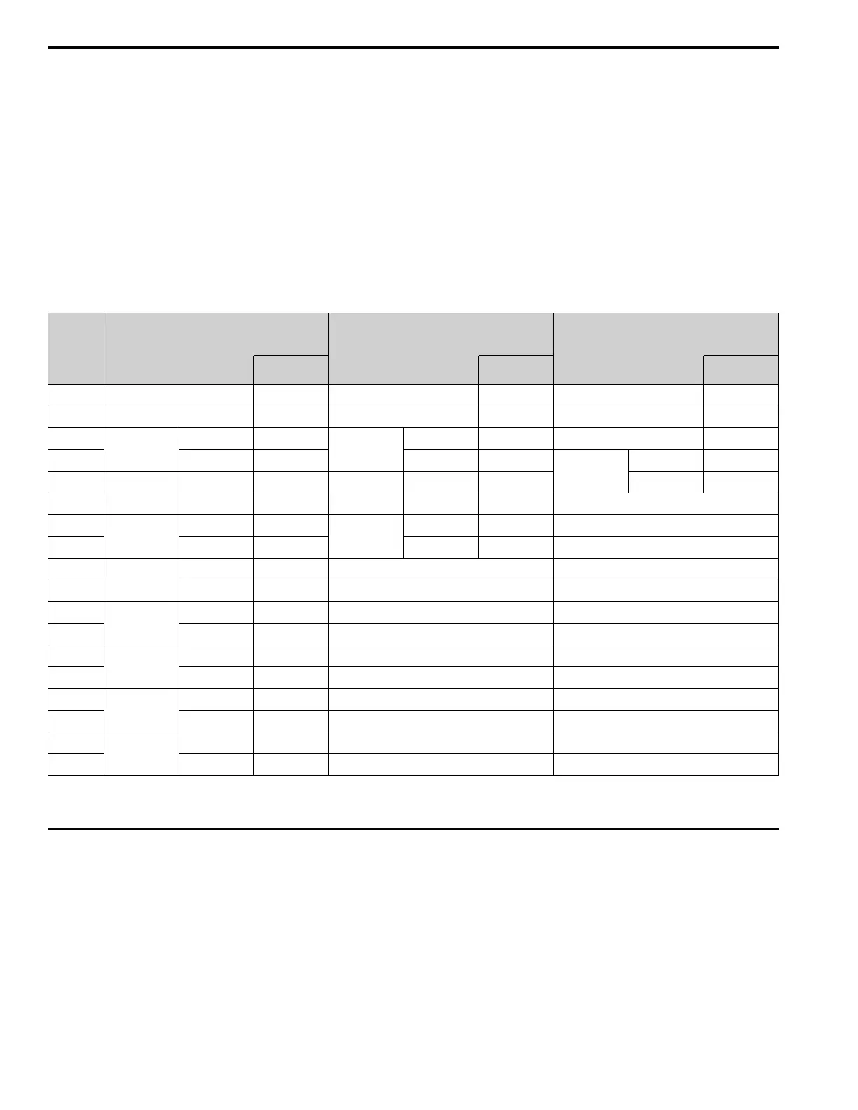
Table 10.28 shows example messages when you write the frequency reference and torque limit from the bypass for
slave 1. Table 10.28 uses these specified holding registers data for the examples.
• 0002H: Frequency Reference = 60.00 Hz (6000 = 1770H)
• 0006H: PID Setpoint = 12.34% (1234 = 04D2H)
If parameter values are changed using the Write command, an Enter command is necessary to activate and save the
data. Refer to H5-11: Comm ENTER Command Mode on page 309 and Enter Command on page 748 for more
information.
Table 10.28 Message Example When Writing to Non-Consecutive Holding Registers
Byte
Command Message Response Message (when normal) Response Message (when there is a fault)
Setting Data
(Hex.)
Setting Data
(Hex.)
Setting Data
(Hex.)
0 Slave address 01 Slave address 01 Slave address 01
1 Function Code 67 Function Code 67 Function Code E7
2
Subfunction
Code
Upper 01
Subfunction
Code
Upper 01 Error Codes 02
3 Lower 0E Lower 0E
CRC-16
Upper EA
4
Data Qty
Upper 00
Data Qty
Upper 00 Lower 31
5 Lower 02 Lower 02 -
6
Byte No.
Upper 00
CRC-16
Upper D5 -
7 Lower 04 Lower FC -
8
Holding register
1 No.
Upper 00 - -
9 Lower 02 - -
10
Holding register
1 data
Upper 17 - -
11 Lower 70 - -
12
Holding register
2 No.
Upper 00 - -
13 Lower 06 - -
14
Holding register
2 data
Upper 04 - -
15 Lower D2 - -
16
CRC-16
Upper 74 - -
17 Lower CD - -
Note:
The number of bytes set in the command message set the data quantity × 2 during the command message.
◆ Enter Command
When you use MEMOBUS/Modbus communications to write parameters from the PLC to the drive, an Enter
command is required to activate and save those parameters. This section gives information about the Enter
commands.
■ Types of Enter Commands
The drive supports the two Enter commands shown in Table 10.29.
Write 0 to register number 0900 or 0910 (Hex.) to enable the Enter command. You can only write to these registers. If
you read to these registers, it will cause an error.

 Loading...


