Electrical Installation
3
3.5 Bypass PCB Control Circuit
YASKAWA SIEPYAIH6B01A HV600 AC Drive Bypass Technical Reference 95
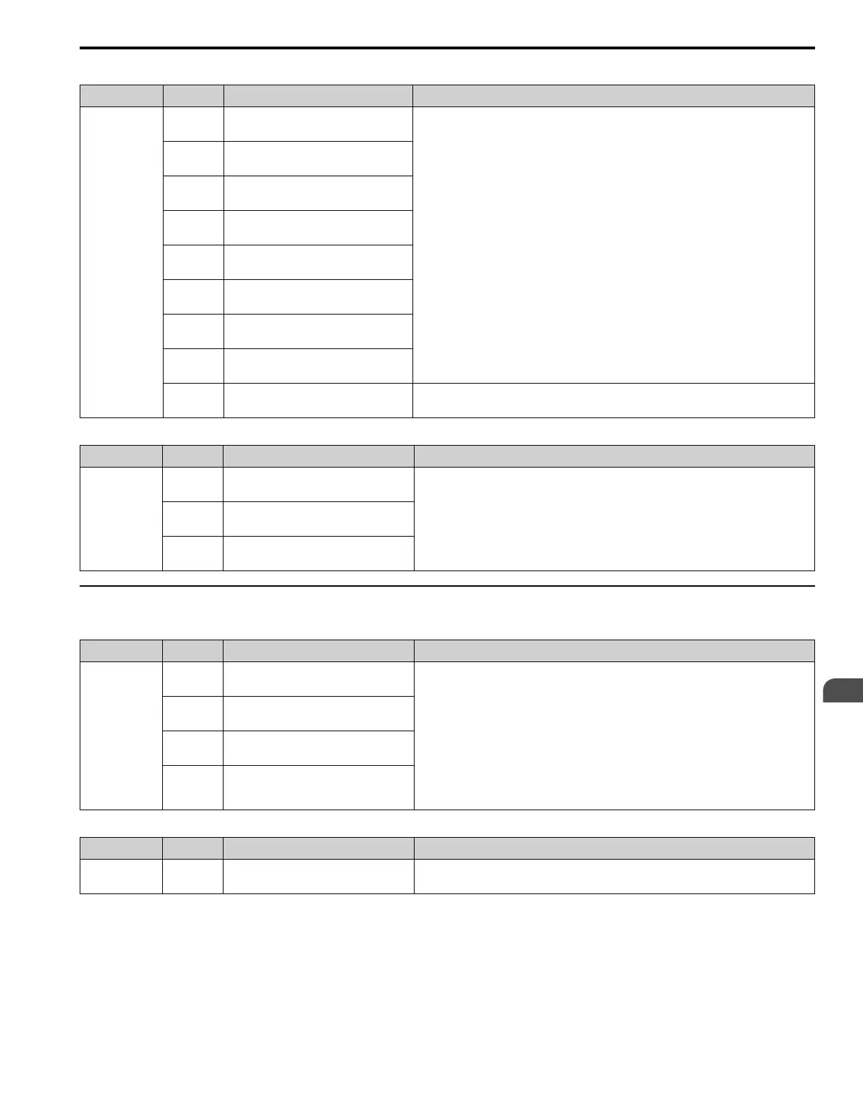
Table 3.14 Bypass Digital Input Terminals (TB2)
Type Terminal Name (Default) Function (Signal Level)
Digital Inputs
TB2-1
DI-1
Digital Input 1
(Run (AUTO))
Dry contact rated, photocoupler sinking input to IG24, 24 Vdc 8 mA,
Ground fault protected
TB2-2
DI-2
Digital Input 2
(Run Enable - Safety (NC))
TB2-3
DI-3
Digital Input 3
(Run Interlock (BAS))
TB2-4
DI-4
Digital Input 4
(Remote Transfer to Bypass)
TB2-5
DI-5
Digital Input 5
(Emergency Override Bypass)
TB2-6
DI-6
Digital Input 6
(-)
TB2-7
DI-7
Digital Input 7
(-)
TB2-8
DI-8
Digital Input 8
(-)
TB2-9/10
IG24
Isolated Ground
Digital input common
Table 3.15 Bypass Analog Input Terminals (TB4)
Type Terminal Name (Default) Function (Signal Level)
Analog Input
TB4-1
+10 Vdc
Analog Input Power Supply
AUTO Mode
Speed Reference
0 to 10 Vdc (20 kΩ) or 4 to 20 mA (250 Ω)
TB4-2
AI
Analog Input Speed Reference
TB4-3
COMMON
Analog Input Common
◆ Bypass Control Circuit Terminal Block Output Functions
Table 3.16 Bypass Digital Output Terminals (TB1)
Type Terminal Name (Default) Function (Signal Level)
Digital Outputs
TB1-1/2/3
DO-7
Digital Output 7
(Motor Run)
Relay, dry contact form C, 30 Vdc or 120 Vac,
DO-7 to DO-10 for customer use, 2 Amp
TB1-4/5/6
DO-8
Digital Output 8
(HAND Mode)
TB1-7/8/9
DO-9
Digital Output 9
(AUTO Mode)
TB1-10/11/
12
DO-10
Digital Output 10
(System Fault)
Table 3.17 Control Circuit Ground Terminals (TB6)
Type Terminal Name (Default) Function (Signal Level)
Ground
TB6-1/2
GROUND
Chassis Ground
-