3.5 Bypass PCB Control Circuit
96 YASKAWA SIEPYAIH6B01A HV600 AC Drive Bypass Technical Reference
◆ Bypass Serial Communication Terminals
Table 3.18 Bypass Serial Communication Terminals (TB3)
Type Terminal Terminal Name Function (Signal Level)
Serial
Communication
TB3-1
IG5
Isolated ground
Ground reference for RS-485 signals. This is an isolated ground used only for communications and may be used in
certain circumstances to connect the floating ground references of other communication devices.
TB3-2
TXRX+
(+) Differential
communication signal
• BACnet communications
• APOGEE FLN communications
• MEMOBUS/ Modbus communications
• Metasys N2 communications
Use an RS-485 cable to connect the drive.
Note:
Make sure that DIP switch S1 is ON to enable the
termination resistor in the last drive in a BACnet,
APOGEE FLN, MEMOBUS/ Modbus, or Metasys
N2 network.
• RS-485
• BACnet communications: Maximum 76.8 kbps
• APOGEE FLN communications: 4.8 or 9.6 kbps
• MEMOBUS/Modbus communications: Maximum
115.2 kbps
• Metasys N2 communications: 9.6 kbps
TB3-3
TXRX-
(-) Differential
communication signal
TB3-4
SHIELD
Shield tie point Capacitively coupled to chassis ground.
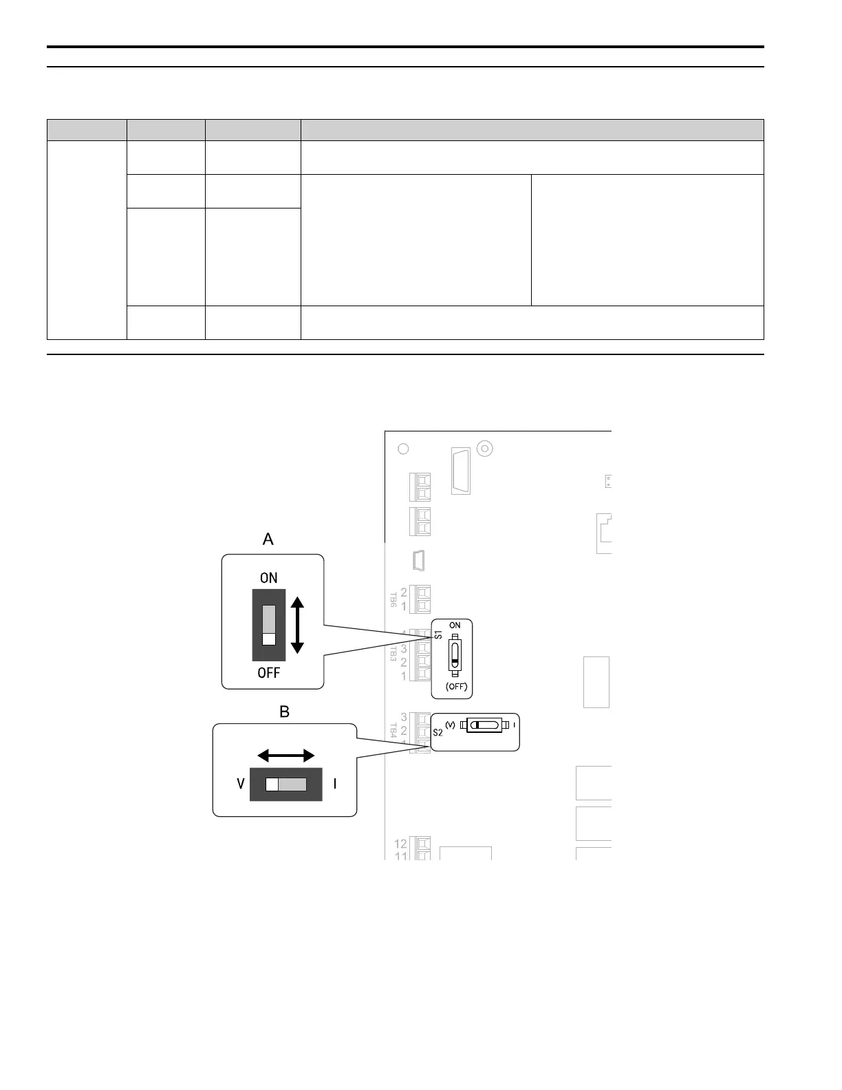
◆ Switches on the Bypass PCB
The bypass PCB has switches to adapt the bypass I/Os to the external control signals as shown in Figure 3.11.
Set the switches to select the functions for each terminal.
Figure 3.11 Locations of Switches