Table 4.26 Constant Output, Settings C to F
Setting = C 90 Hz Setting = D 120 Hz Setting = E 180 Hz Setting = F 60 Hz
0
6
12
200
1.5 3 9060
Voltage (V)
Frequency (Hz)
0
6
12
200
1.5 3 12060
Voltage (V)
Frequency (Hz)
0
6
12
200
1.5 3 18060
Voltage (V)
Frequency (Hz)
0
6.9
230
1.5 3 60
13.8
Voltage (V)
Frequency (Hz)
Setting a Custom V/f Pattern (Setting F: Default)
Setting parameter E1-03 to F allows the user to set up a custom V/f pattern by changing parameters E1-04 to E1-13.
When initialized, the default values for parameters E1-04 to E1-13 will be equal to Predefined V/f pattern 1.
n
V/f Pattern Settings E1-04 to E1-13
If E1-03 is set to a preset V/f pattern (i.e., a value other than F), the user can monitor the V/f pattern in parameters E1-04
through E1-13. To create a new V/f pattern, set E1-03 to F. Refer to V/f Pattern on page 106 for an example custom V/f
pattern.
No. Parameter Name Setting Range Default
E1-04 Maximum Output Frequency 40.0 to 400.0 Hz 60.0 Hz
E1-05 Maximum Voltage
0.0 to 255.0 V
<4>
575.0 V
E1-06 Base Frequency 0.0 to [E1-04] 60.0 Hz
E1-07 Middle Output Frequency 0.0 to [E1-04] 3.0 Hz
E1-08 Middle Output Frequency Voltage
0.0 to 255.0 V
<4>
15.0 V
E1-09 Minimum Output Frequency 0.0 to [E1-04] 1.5 Hz
E1-10 Minimum Output Frequency Voltage
0.0 to 255.0 V
<4>
9.0 V
E1-11 Middle Output Frequency 2 0.0 to [E1-04]
0.0 Hz
<6>
E1-12 Middle Output Frequency Voltage 2
0.0 to 255.0 V
<4>
0.0 V
<5>
<6>
E1-13 Base Voltage
0.0 to 255.0 V
<4>
0.0 V
<5>
<7>
<4> Values shown are specific to 200 V class drives. Double the value for 400 V class drives. Multiply the value by 2.875 for 600 V class drives.
<5> The drive changes these settings when Auto-Tuning is performed (Rotational Auto-Tuning, Stationary Auto-Tuning 1, 2).
<6> Parameter ignored when E1-11 and E1-12 are set to 0.0.
<7> E1-13 and E1-05 are set to the same value when Auto-Tuning is performed.
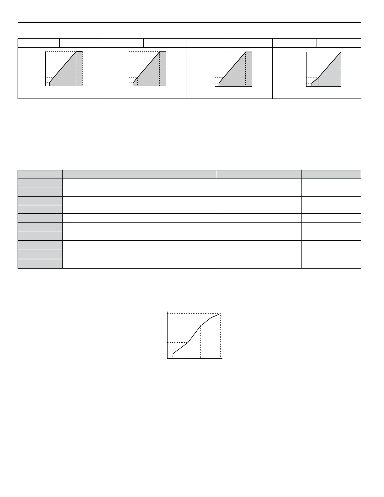
Output Voltage (V)
Frequency (Hz)
E1-05
E1-12
E1-13
E1-08
E1-10
E1-09 E1-07 E1-06 E1-11 E1-04
Figure 4.18 V/f Pattern
Note: 1. The following condition must be true when setting up the V/f pattern: E1-09 ≤ E1-07 < E1-06 ≤ E1-11 ≤ E1-04
2. To make the V/f pattern a straight line below E1-06, set E1-09 equal to E1-07. In this case the E1-08 setting is disregarded.
3. E1-03 is unaffected when the drive is initialized, but E1-04 through E1-13 return to their default values.
4. Only use E1-11, E1-12, and E1-13 to fine-tune the V/f pattern in the constant output range. These parameters rarely need to be changed.
n
E2-01: Motor Rated Current
Provides motor control, protects the motor, and calculates torque limits. Set E2-01 to the full load amps (FLA) stamped on
the motor nameplate. If Auto-Tuning completes successfully, the value entered to T1-04 will automatically be saved to E2-01.
4.6 Basic Drive Setup Adjustments
106
YASKAWA ELECTRIC TOEP YAIP1U 01B YASKAWA AC Drive - P1000 Quick Start Guide

 Loading...


