n
b1-01: Frequency Reference Selection 1
Selects the frequency reference source 1 for the REMOTE mode.
Note: 1. If a Run command is input to the drive but the frequency reference entered is 0 or below the minimum frequency, the RUN indicator
LED on the digital operator will light and the STOP indicator will flash.
2. Press the LO/RE key to set the drive to LOCAL and use the operator keypad to enter the frequency reference.
No. Parameter Name Setting Range Default
b1-01 Frequency Reference Selection 1 0 to 4 1
Setting 0: Operator keypad
Using this setting, the frequency reference can be input by:
•
switching between the multi-speed references in the d1-oo parameters.
• entering the frequency reference on the operator keypad.
Setting 1: Terminals (analog input terminals)
Using this setting, an analog frequency reference can be entered as a voltage or current signal from terminals A1, A2, or A3.
Voltage Input
Voltage input can be used at any of the three analog input terminals. Make the settings as described in Table 4.8 for the input
used.
Table 4.8 Analog Input Settings for Frequency Reference Using Voltage Signals
Terminal Signal Level
Parameter Settings
Notes
Signal Level
Selection
Function Selection Gain Bias
A1
0 to 10 Vdc H3-01 = 0
H3-02 = 0
(Frequency Reference Bias)
H3-03 H3-04 –
-10 to +10 Vdc H3-01 = 1
A2
0 to 10 Vdc H3-09 = 0
H3-10 = 0
(Frequency Reference Bias)
H3-11 H3-12
Set jumper S1 on the terminal
board to “V” for voltage input.
-10 to +10 Vdc H3-09 = 1
A3
0 to 10 Vdc H3-05 = 0
H3-06 = 0
(Frequency Reference Bias)
H3-07 H3-08
Set DIP switch S4 on the
terminal board to “AI”.
-10 to +10 Vdc H3-05 = 1
Drive
A1 Analog Input 1
0 to 10 V
AC Analog input common
2 k
+V
10.5 V, 20 mA power supply
A2 Analog Input 2
A3 Analog Input 3
Drive
A1 Analog Input 1
AC Analog input common
+V
10.5 V, 20 mA power supply
A2 Analog Input 2
A3 Analog Input 3
4 k
-10 to 10 V
OR
Customer
+/- 10 V
Supply
+10 V
-10 V
Common
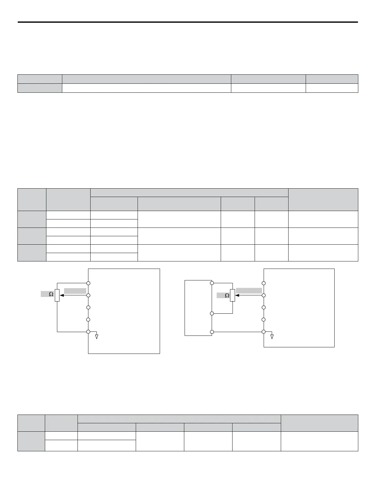
Figure 4.6 Setting the Frequency Reference as a Voltage Signal at Terminal A1
Current Input
Input terminals, A1, A2, and A3 can accept a current input signal. Refer to Table 4.9 for an example to set terminal A2 for
current input.
Table 4.9 Analog Input Settings for Frequency Reference Using a Current Signal
Terminal
Signal
Level
Parameter Settings
Notes
Signal Level Selection Function Selection Gain Bias
A2
4 to 20 mA H3-09 = 2
H3-10 = 0
(Frequency Bias)
H3-11 H3-12
Make sure to set jumper S1 on the
terminal board to “I” for current
input.
0 to 20 mA H3-09 = 3
4.6 Basic Drive Setup Adjustments
92
YASKAWA ELECTRIC TOEP YAIP1U 01B YASKAWA AC Drive - P1000 Quick Start Guide
 Loading...


