Drive
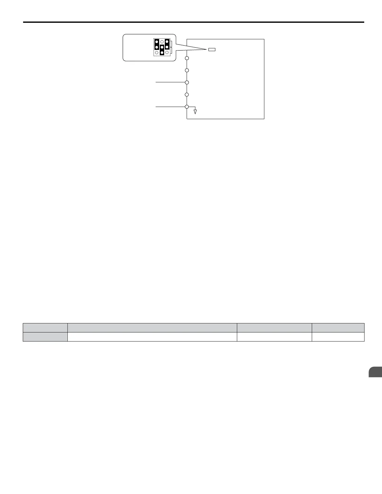
A1 Analog Input 1
0 or 4 to 20 mA
AC Analog input common
+V
10.5 V, 20 mA power supply
A2 Analog Input 2
A3 Analog Input 3
Jumper S1
A1/A2/A3
Voltage/Current
Selection
V
I
A1 A2 A3
Figure 4.7 Setting the Frequency Reference as a Current Signal to Terminal A2
Switching between Main/Auxiliary Frequency References
The frequency reference input can be switched between the analog terminals A1, A2, and A3 using multi-speed inputs. Refer
to Multi-Step Speed Selection on page 101 for details on using this function.
Setting 2: MEMOBUS/Modbus Communications
This setting requires entering the frequency reference via the RS-485/422 serial communications port (control terminals R+,
R-, S+, S-).
Setting 3: Option card
This setting requires entering the frequency reference via an option board plugged into connector CN5-A on the drive control
board. Consult the option board manual for instructions on integrating the drive with the communication system.
Note: If the frequency reference source is set for Option PCB (b1-01 = 3), but an option board is not installed, an oPE05 Operator Programming
Error will be displayed on the digital operator and the drive will not run.
Setting 4: Pulse Train Input
This setting requires a pulse train signal to terminal RP to provide the frequency reference. Follow the directions below to
verify that the pulse signal is working properly.
Verifying the Pulse Train is Working Properly
• Set b1-01 to 4 and set H6-01 to 0.
• Set the H6-02 to the pulse train frequency value that equals 100% of the frequency reference.
• Enter a pulse train signal to terminal RP and check for the correct frequency reference on the display.
n
b1-02: Run Command Selection 1
Determines the Run command source 1 in the REMOTE mode.
No. Parameter Name Setting Range Default
b1-02 Run Command Selection 1 0 to 3 1
Setting 0: Operator
This setting requires entering the Run command via the digital operator RUN key and also illuminates the LO/RE indicator
on the digital operator.
Setting 1: Control Circuit Terminal
This setting requires entering the Run command via the digital input terminals using one of following sequences:
• 2-Wire sequence 1:
Two inputs (FWD/Stop-REV/Stop). Set A1-03 to 2220 to initialize the drive and preset terminals S1 and S2 to these
functions. This is the default setting of the drive.
• 2-Wire sequence 2:
Two inputs (Start/Stop-FWD/REV).
• 3-Wire sequence:
Three inputs (Start-Stop-FWD/REV). Set A1-03 to 3330 to initialize the drive and preset terminals S1, S2, and S5 to these
functions. Refer to Setting 0: 3-Wire Sequence on page 108.
4.6 Basic Drive Setup Adjustments
YASKAWA ELECTRIC TOEP YAIP1U 01B YASKAWA AC Drive - P1000 Quick Start Guide
93
4
Start-Up Programming &
Operation