< 1. Overview >
1-3
IM 12F5A1-01E
1.2 MeasuringPrincipleofFC400GFreeAvailable
Chlorine Analyzer
The FC400G free available chlorine analyzer applies the polarographic method using a rotating
electrode,asthemeasuringprincipletomeasurefreeavailablechlorineexistingintheformofchlorine
(Cl
2
),hypochlorousacid(HClO),andhypochloriteions(ClO
-
).
TheFC400Gappliesexternalvoltagebetweentheindicatorelectrode(rotatingelectrode)and
counter electrode (silver chloride electrode) to electrolytically reduce free available chlorine, and then
measuresthediusioncurrentowduringtheabovevoltageapplicationtoobtaintheconcentration
of free available chlorine. The voltage to be applied is selected from among values in the area where
current value remains stable even if the voltage value changes, i.e., the area (plateau area) where
concentration polarization occurs in polarography. Since this applied voltage changes according
tothediusioncurrentvalue,theFC400Gfreeavailablechlorineanalyzerperformscompensation
complyingwiththischange,toapplysuitablevoltage.Further,thisobtaineddiusioncurrentvalue
also changes with temperature, and the current is automatically corrected using signals from the RTD
(Pt1000Ω)builtinthecounterelectrode.
The FC400G free available chlorine analyzer was designed to require minimal maintenance and uses
noreagent.However,itmustbeunderstoodthattherearerestrictionsontheconditionsofthewaterto
be measured (sample) in comparison with the RC400G Residual Chlorine Analyzer that uses reagent.
Also,notethatifcombinedchlorineispresentinsample,FC400Gperformanceisaected.
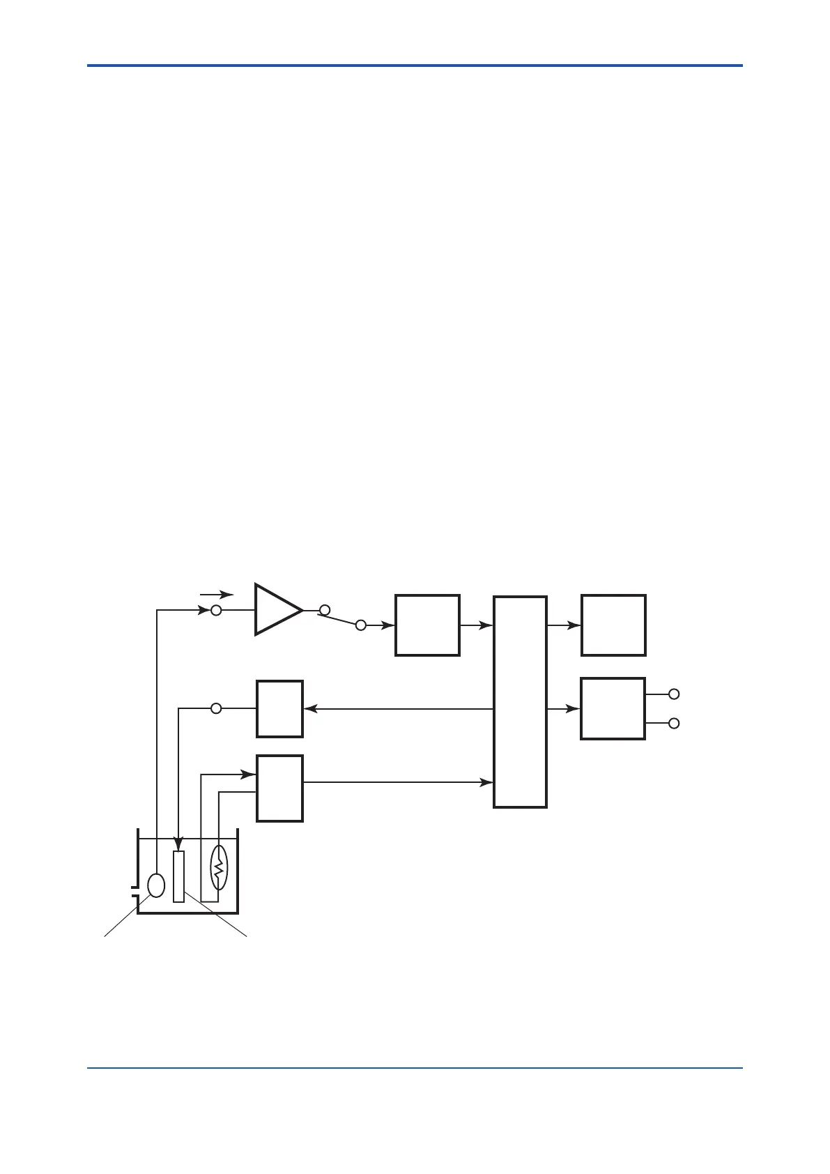
Figure 1.2 shows the measuring circuit principle of the FC400G free available chlorine analyzer. The
FC400Gappliesvoltagecompensatedinaccordancewiththediusioncurrentvalue,betweenthe
indicatorandcounterelectrodesandmeasuresthediusioncurrentowbetweentheelectrodes.
Temperature compensation is accomplished using the CPU which performs calculation based on the
temperature signals received from the temperature-measuring circuit.
F1.2e.ai
Is
ME
Current/
voltage
conversion
circuit
Voltage
apply-
ing
circuit
Tempe-
rature-
measur-
ing
circuit
RE (Applied-voltage
compensation)
Measuring tank
Indicator Electrode Counter Electrode
CPU
LCD
Current/
voltage
output
circuit
4 to 20 mA or
1 to 5 V
Figure1.2 MeasuringCircuitPrinciple

 Loading...


