< 6. Operation >
6-2
IM 12F5A1-01E
6.1.3 SupplyingSampleWater
Beforestartingtosupplywatertobemeasured,conrmthattheneedlevalvesintheFC400Gandthe
samplingsystemareclosed.Whenit’sdiculttoviewtheliquidsurfaceinthemeasuringtankfrom
outside,checkthetankwhenit’stimeforelectrodemaintenance(refertoFigure6.3).
(1) When there is no Sampling System
ThesamplesupplypressuretotheFC400Gshouldbe1to150kPa,andowshouldbe0.1to
2.5 l/min.
Next,slowlyopentheneedlevalveoftheFC400Gtoadjustthewaterow.
• Thewatershouldowcontinuouslyalongthewholelengthoftheelectrode,fromthetipto
whereitentersthewater(minimumow0.1l/min.)
• Liquidowshouldnotbesuchthatwatersplashesonthebaseoftheelectrode(maximum
ow2.5l/min.)Checkthatthereisnoleakagefromthepipingorfromthebreatherholeofthe
tank.
(2) When the FC400G is used with ST401G Sampling System.
Thesamplesupplypressureshouldbe100to750kPa,andowshouldbe0.1to10l/min.Adjust
owusingneedlevalveasdescribedin(1)above.
(Note) Refer to the Instruction Manual IM12A0V2-E of the ST401G Sampling System.
6.1.4 PolishingtheIndicatorElectrode
The electrode surface of the indicator electrode must always be kept clean. Polish the electrode
surface as follows:
(1) Press the
MODE
key on the converter to enter the operation level and press the
YES
NO
key to select the <CELL> mode (cell motor ON / OFF). Press the
NO
key with respect to the
message “CELL ON” displayed to stop the rotation of the indicator electrode.
Whentheelectrodestopsrotating,theCELLlampextinguishes.
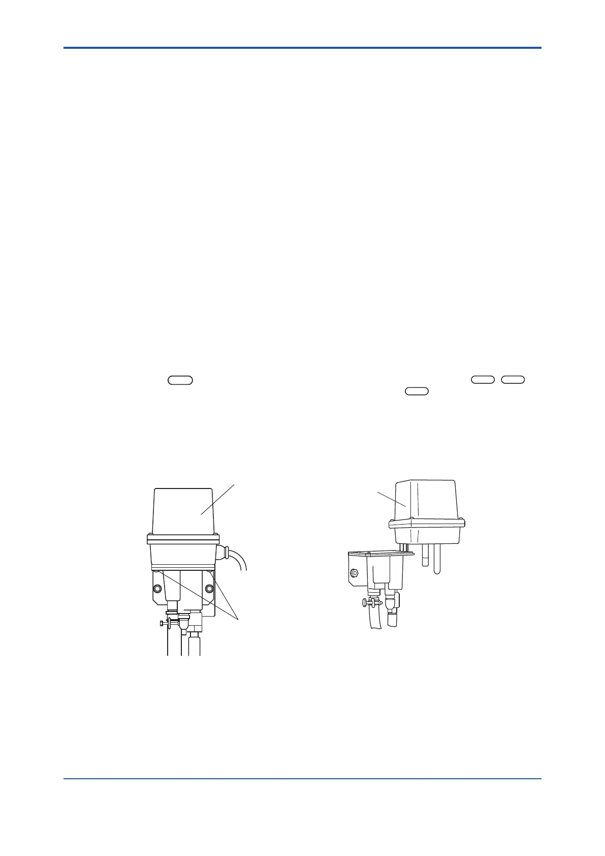
Remove the electrode mechanism block from the measuring tank and set up the block as shown
inFigure6.3.Theelectrodemechanismblockisxedtothemeasuringtankusingtwoscrewsat
the lower part of the mechanism block.
Fixing screws
(2 pcs)
Electrode
mechanism block
F6.3e.ai
Electrode mechanism
block cover
Figure6.2 ElectrodeMechanism Figure6.3 UnderMaintenance
BlockFixingScrews

 Loading...


