< 3. Installation, Piping and Wiring >
3-1
IM 12F5A1-01E
3. INSTALLATION,PIPING,ANDWIRING
3.1 Installation
TheFC400Gfreeavailablechlorineanalyzer(non-reagenttype)issucientlypackedforshipmentto
prevent damage during transportation.
Upon receipt, carefully unpack the FC400G carton near the place of installation.
3.1.1 InstallationSite
Install the FC400G free available chlorine analyzer at a location that:
(1) is free from rain water such as an indoor location or in a cabinet,
(2) has low vibration,
(3) has low corrosive gas,
(4) is low humidity,
(5) has low temperature variation and where the temperature is maintained at or as near to room
temperature as possible,
(6)allowssucientmaintenancespacewitheasymaintenanceaccess,and
(7) allows drainage.
3.1.2 Mounting
The FC400G Non-Reagent type Free Available Chlorine Analyzer mounts vertically or horizontally on
asturdypipe(JIS50A),usingUbolts(seediagram).Tomountitonaplateorwall,drillM8-sizeholes,
separated by 70 mm, for the U-bolt holes.
Wherenecessary,useasamplingsystemtoregulatethepressureandowofthemeasurement
liquid. Normally the FC400G would be mounted in the sampling system in this case.
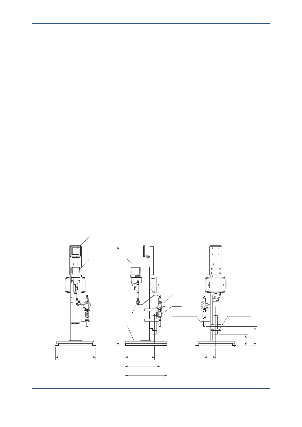
Figure 3.1 shows a combination of the FC400G with a special sampling system (ST401G-FC4).
When using this, refer to its instruction manual IM12A0V2-E regarding installation requirements.
F3.1.2.ai
FC400G
PVC tray
PR1 : Pressure reducing valve
NV1 : Needle valve
BV1 : Ball valve
455
150
385
253
150
530
550
Approx. 1312
NV1
BV1
PR1
VP16 pipe
Sample
water inlet
Converter
Detector
Drain outlet
VP40 pipe
Unit: mm
Figure3.1 ExampleofST401G-FC4Installation

 Loading...


