< 6. Operation >
6-3
IM 12F5A1-01E
(2) Removing the Indicator Electrode
Removetheelectrodemechanismblockcoverfromthedetector.Holdthegearssothatthe
drive shaft does not turn and remove the indicator electrode. The electrode is screwed into the
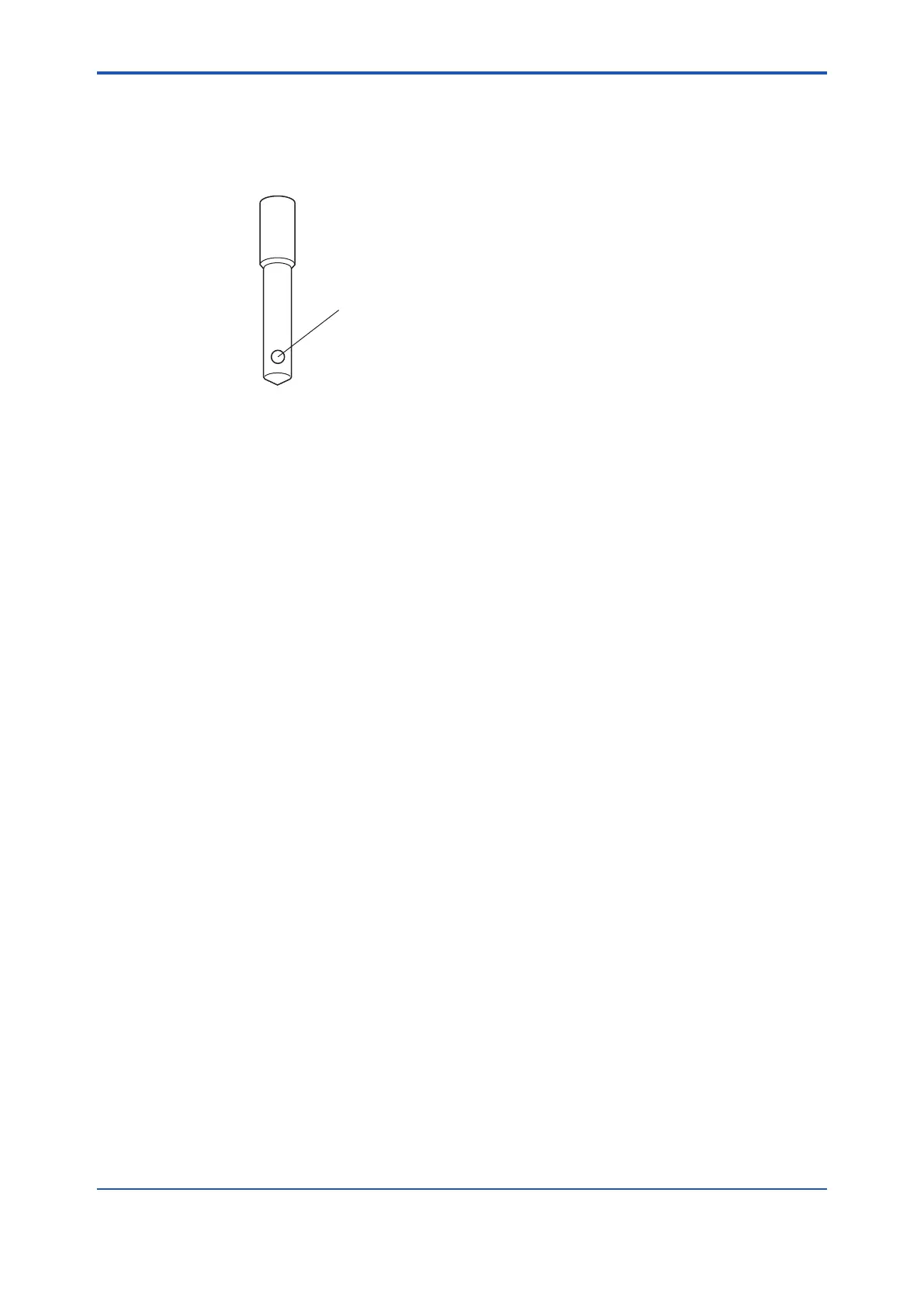
drive shaft; turn the electrode counterclockwise. This time, do not touch the rotating contact. The
deformed rotating contact disables electrode function.
Figure6.4 AppearanceoftheIndicatorElectrode
(3) Polishing the Electrode Surface of the Indicator Electrode
Spread the provided abrasive (alumina) onto dampened gauze and thoroughly clean the
electrode surface using such gauze so that any contamination such as oil and grease is
completelyremoved.Thenwashoanyabrasivesadheringtotheelectrodeincleanrunning
water.
Afterpolishingandcleaning,conrmthatcontaminationhasbeencompletelyremoved.
The clean electrode surface must be uniformly wetted.
Note: Polish the electrode surface (gold electrode) by following the instructions below when it has
become corrugated or deformed from the original shape (about 3 mm in diameter).
Polishtheelectrodesurfacewithsandpaper(about#600)untilthesurfacebecomesnally
rounded. Then, polish it with sandpaper (about #2000), and lastly with polishing powder
(alumina). Make sure the electrode surface is clean and then install the indicator electrode.
Reduce the amount of ceramic beads if the electrode has deformed greatly. The ceramic
beadsshouldbelledupto5mmunderthebottommostnotchofthebeadscasewhenthe
indicator electrode is inserted.
(4) Installing the Indicator Electrode
Holdthegearssothatthedriveshaftdoesnotturn,andsucientlyscrewtheelectrodeintothe
shaft.Duringinstallation,exercisecarenottotouchtheelectrode surface.
Note: Polish the electrode surface again if you have touched it.
(5) Attach the electrode mechanism cover. Then, set the electrode mechanism block to the
measuringtankinplaceandfastenitusingthexingscrews.Finally,usethe<CELL>modein
the operation level to rotate the electrode.
6.1.5 SupplyingPower
Before supplying power, check that the fuse holder cap in the converter is not loose.
A power switch in the power line to the FC400G is used to turn power ON / OFF (the FC400G does
not have any internal power switch). Be careful not to turn on the power and cause an accident with
the indicator electrode or belt used to rotate it when the cover is removed or the electrodes are parked
inthemaintenancepositionshowninFigure6.3
(Note) When power is supplied, the instrument enters measurement mode.

 Loading...


