< 3. Installation, Piping and Wiring >
3-3
IM 12F5A1-01E
3.2.2 ForUsewithDedicatedSamplingSystem
Piping is connected to the measurement liquid inlet and drain outlet. The piping will depend on the
sampling equipment. When the ST401G sampling system is to be used, refer to its instruction manual
IM12A0V2-E.
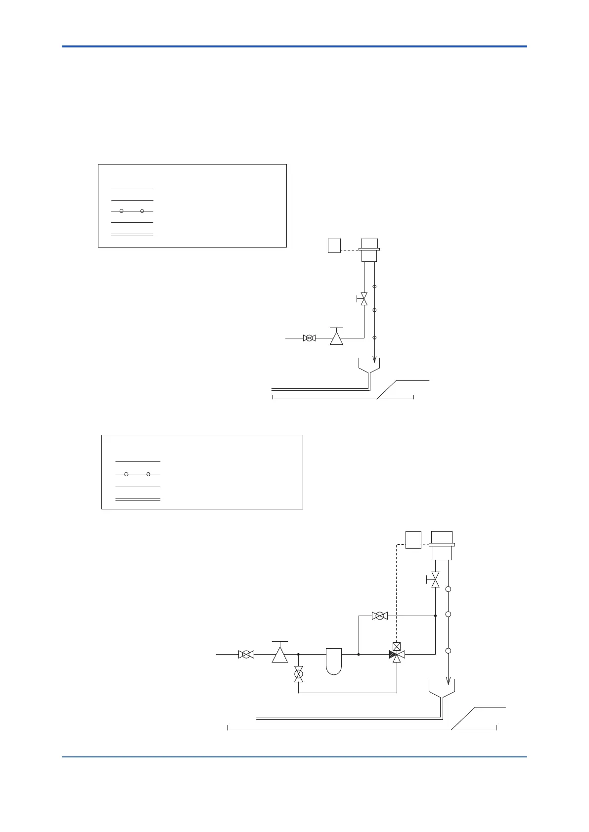
Figure3.3showsanexampleofpipingfortheST401GSamplingSystem.
For details, refer to IM 12A0V2-E Sampling System.
Piping diagram of ST401G-FC4-N-A (With free available chlorine analyzer)
<Tubing materials>
=
=
XX
φ22 / φ15 soft tube with net
(VP40)
Drain
VP16 Pipe
PipeVP40
φ6 / φ4 Polyethylene tube
PR1 : Pressure-reducing valve
FCC : Free available chlorine converter
FCD : Free available chlorine detector
NV1 : Needle valve
BV1 : Ball valve
NV1
FCC
=
X
(VP16)
Measuring water
=
FCD
BV1
PR1
PVC tray
φ12 / φ9 Polyethylene tube
=
PipingdiagramofST401G-FC4-N-A/AZC¨
(Withautozerocalibrationforfreeavailablechlorineanalyzer)
(VP40)
Drain
=
=
=
=
=
=
=
=
=
=
BV2
NO
COM
NC
F1
SV1
X
NV1
FCC
=
X
(VP16)
Measuring water
=
FCD
BV1
PR1
BV3
PVC tray
<Tubing materials>
=
=
XX
φ22 / φ15 soft tube with net
VP16 pipe
pipeVP40
φ6 / φ4 Polyethylene tube
BV1,2,3 : Ball valve
PR1 : Pressure-reducing valve
FCC : Free available chlorine converter
FCD : Free available chlorine detector
NV1 : Needle valve
F1 : Activated charcoal filter
SV1 : 3-way solenoid valve
Figure3.3 PipingDiagramofST401GSamplingSystem

 Loading...


