< 8. Maintenance >
8-8
IM 12F5A1-01E
the lengthwise direction.
(10) Place a plate that prevents friction dust from entering the electrode holder. With the two
bumpsontheplatefacingdown,passtheplateunderthedrivenshaftandindexthetwo
bumps with the two holes in the plate mounted in step (11). Then, as a temporary measure,
loosely tighten the two screws that hold it in place.
(11) Mount the rotating contact on the driven shaft.
(Note) The driven shaft and rotating contact need to be in contact and make a good electrical connection, so make sure
thattheyareclean.However,adherehceoflubricantfortherotatingcontacttothesurfacedoesnotinterferewiththe
peformance.
(12) With the drive belt mounted, attach pulleys to the drive shaft and driven shaft.
(Note) Installthedriveshaftpulleysothatthetipoftheshaftcanprojectout0.3to0.7mmfromendoftheshaft,sothatdrive
belt becomes horizontal.
(13)Whileadjustingthedrivebelttension,furthertightenthescrewsthatweretightened
temporarily in steps (9) and (10).
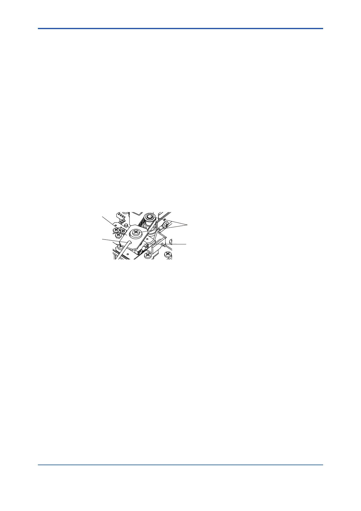
SetthespringplateandthebelttensionadjusterplateasFigure8.6shows.
Hangthehookofaspringbalance(1.00kg)ontheholeinthedrivenshaft.Makesurethat
all the temporarily tighten four screws are loose.
Draw the drive belt horizontally in the direction of the line that connects between the drive
shaft and the driven shaft, by a force of 4 N (spring balance reading of 0.4 kgf). With this
tension kept, tighten the screws completely.
Fastenthescrewstosetthefrictiondustprotectionplate.Afterthescrewsarexed,remove
thebelttensionadjuster.
Rotating contact
Pulleys
spring plate hook
adjuster plate
Figure8.6 Setupofbelttensionadjustment
(14) Mount indicator electrode on driven shaft, and check that indicator electrode is not
contacting the base.
(Note) If the indicator electrode is contacting the base, or if the hole in the center of the base and the center of the indicator
electrodearenotaligned,loosethefourscrewsonthemotormountingbaseandadjust.
(15) Remountcounterelectrode,reconnectwiringinplace,andxclamp.
This completes the replacement procedure. Feed power to FC400G. Check that the drive
shaft/drive belt/driven shaft rotates smoothly and there is no abnormal noise like vibration or
intermittent sound.

 Loading...


