48
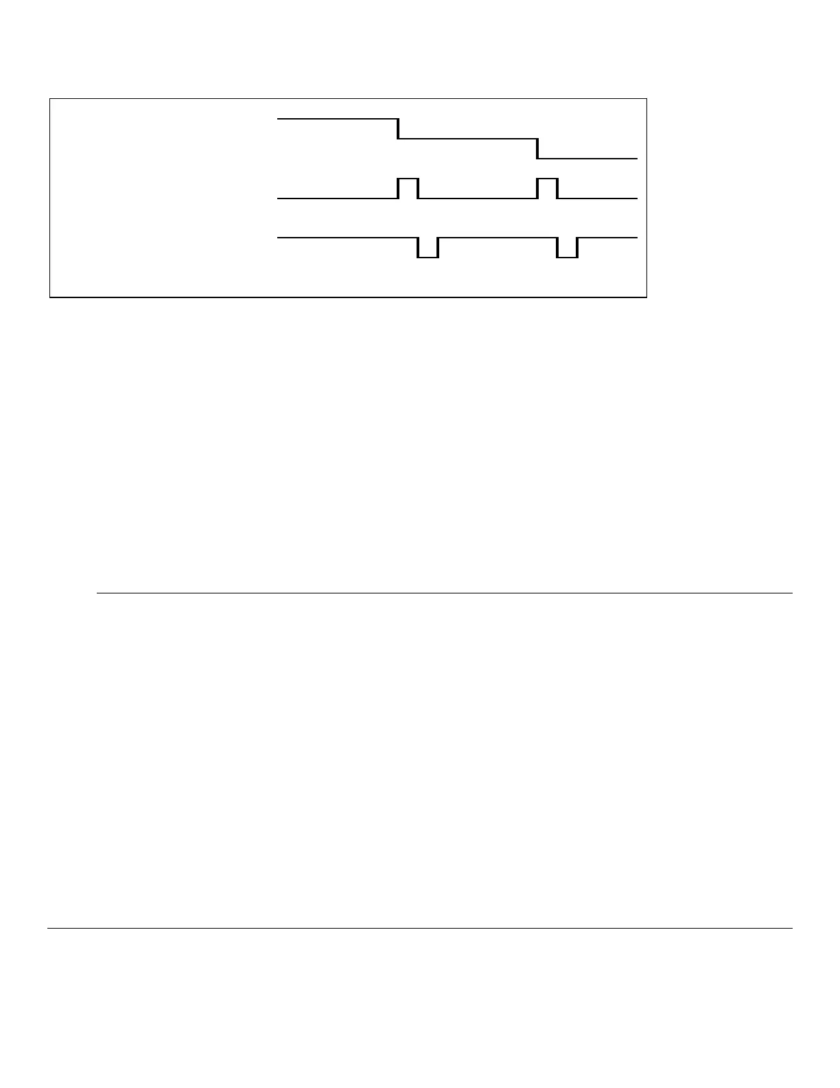
Figure 6.7
6.4.2 Pump Control Outputs
Three discrete outputs are provided on the 2960 which are intended to control external pumps. The means of control is on
or off only, no intermediate states are supported. The three outputs are labeled Feed Pump A, Feed Pump B, and Filtrate
Pump. All of these outputs are electrically identical and are designed as control signals only, i.e. they are incapable of
driving any pumps directly. These signals must be buffered externally in a manner appropriate to the nature of the pumps
being used. These output signals transition between +5 volts and 0 volts nominally. The logic of each, i.e. whether 5 volts
turns on or off the external device, is selectable (See 6.5 Monitor Setup).
6.4.3 Auxiliary Connector / Signal List
On the back of the 2960 is the 15 pin "D" type connector where the signals emanate. The following table relates the
signals with the connector pin positions and cable wire colors.
2960 Signal Pin# Wire color
Ground 1 Black/White
Ground 2 Orange/Black
Ground 3 Blue/Black
Ground 4 Red/White
Ground 5 Black
Channel B Ready 6 White
Channel A Pump Control 7 Green/White
SysErr 8 Blue/White
Channel A Analog Output 9 Green/Black
Channel B Analog Output 10 Green
Channel B Pump Control 11 Red/Black
Filtrate Pump Control 12 Red
+12V Power Out 13 Blue
Ack\ 14 White/Black
Channel A Ready 15 Orange
Chassis Ground None Shield
Monitor Setup 6.5
1. From the Run menu, touch the [Monitor] tab.
2. Touch the [Configure] button