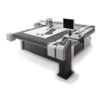
Setting up the control panel/workstation
20
3 Video signal cable (ICC camera) 8 EMERGENCY STOP control device cable
(power unit, EMM_CON_BOARD S13)
4 Operating unit cable (electronics unit, BF
board S16)
9 EMM_CON_BOARD
5 Signal light cable (electronics unit,
Varioface_2)
10 J2 – J3
A Plug in the new, longer LAN cable.
B Plug in the new, longer video signal cable.
C Mount the earthing cable in the electronics unit.
D Plug the new, longer operating unit cable into the ACS_BF_BOARD S16.
E Connect the extension cable of the signal lights to Varioface 2. Mount the ferrite.
Varioface_2 clamp Cord
1 white
3 brown
4 green
5 yellow
6 gray
F Plug the EMERGENCY STOP control device cable into EMM_CON_BOARD S13.
G Check if jumpers J2 and J3 have been removed from the EMM_CON_BOARD.
H Check if the strapping plug has been plugged into EMM_CON_BOARD S11, S12 and S14.
I Lay the cables next to the electronics unit and combine them into a strand.
J Lay the cable strand to the control panel/workstation.
5.3 Positioning the control panel / workstation
The position of the control panel / workstation is predetermined by the length of the connection cable.
The following conditions must be met:
• The distance to the side support must be at least 180 mm
• The electronics unit must still be easy to access
Setting up the control panel / workstation at a distance of 500 mm from the side support and aligned
flush in the front with the side support is recommended.