Cutter with BHS 150
87
Note:
If only the feeder but not the stacker is attached to the cutter, the drilling templates for the cutter
with material transport must be used for the discharge side (front, stacker).
A Place the two drilling templates according to the labeling on the bases on one side of the cutter.
For example, front left and rear left.
B Align the drilling templates to the base frame.
a) Use a bracket, string or a long, straight board, for example, as an aid.
b) Place the aid along the support line for alignment and on the feet.
C Mark the drill holes. Make sure to use the holes with the appropriate marking (1 = front, 2 = rear).
D Mark the drill holes on the opposite side in the same way.
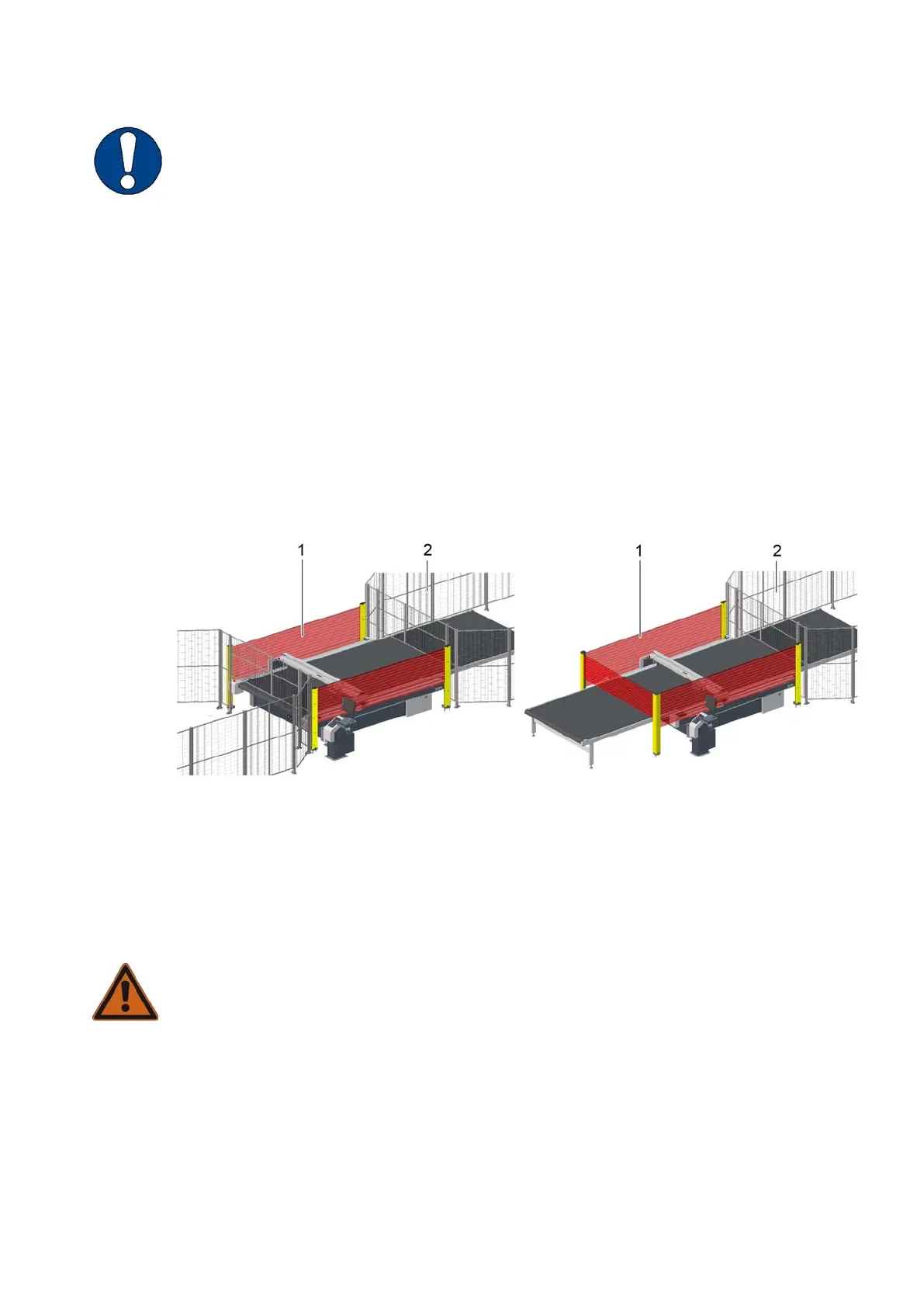
11.2 Connecting the light barrier transmitter and receiver
In the version with the BHS 150, access to the cutter is prevented by a barrier. As a result, the light
curtain is not needed either on one or both sides, depending on the design.
Cutter with two light curtains
(BHS 150 feeder and stacker)
Cutter with three light curtains
(BHS 150 feeder and front CE)
1 Light curtain
2 Barrier
Warning:
The cutter with the 120 mm clearance must only be operated with an enclosing precautionary
measure, which blocks access from all sides during operation. This can be accomplished with
light curtains or mechanical barriers.
Notes on installing the cables:
• The cables to the light barrier transmitters and receivers must be installed on-site.
• The cables are labeled.
• The cables for the front right pillar (TFR, RFR) are laid in the right side support to the pillar.