Chapter 51 PoE Commands
Ethernet Switch CLI Reference Guide
215
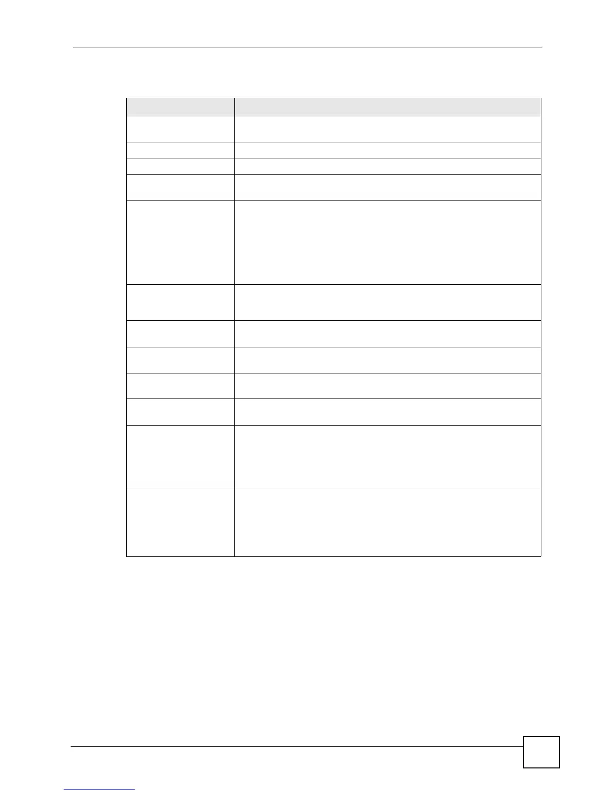
The following table describes the labels in this screen.
Table 121 show pwr
LABEL DESCRIPTION
Averaged Junction
Temperature
This field displays the internal temperature of the PoE chipset.
Port This field displays the port number.
State This field indicates whether or not PoE is enabled on this port.
PD This field indicates whether or not a powered device (PD) is allowed to
receive power from the Switch on this port.
Class This field displays the maximum power level at the input of the PoE-
enabled devices connected to this port. The range of the maximum power
used by the PD is described below.
0: 0.44~12.95 W
1: 0.44~3.84 W
2: 3.84~6.49 W
3: 6.49~12.95 W
Priority When the total power requested by the PDs exceeds the total PoE power
budget on the Switch, the Switch uses the PD priority to provide power to
ports with higher priority.
Consumption (mW) This field displays the amount of power the Switch is currently supplying to
the PoE-enabled devices connected to this port.
MaxPower(mW) This field displays the maximum amount of power the Switch can supply to
the PoE-enabled devices connected to this port.
Total Power This field displays the total power the Switch can provide to PoE-enabled
devices.
Consuming Power This field displays the amount of power the Switch is currently supplying to
the PoE-enabled devices.
Allocated Power This field displays the total amount of power the Switch has reserved for
PoE after negotiating with the PoE device(s).
Note: If the management mode is set to Consumption, this
field shows NA.
Remaining Power This field displays the amount of power the Switch can still provide for PoE.
Note: The Switch must have at least 16 W of remaining power
in order to supply power to a PoE device, even if the
PoE device requested less than 16 W.
 Loading...