Z Measure – the option used to test and set a correct Z Offset value. Once the Z Measure key is pressed, the printer
detects the T0 head position by using load cells. Then, in the same place it takes the same measurement for T1 position.
The dif ference resulting from the measurement is saved in the Z Offset box. To conrm the measurement, press the Save.
Reset – restores the default deviation values.
Save – saves the introduced changes to printer memory.
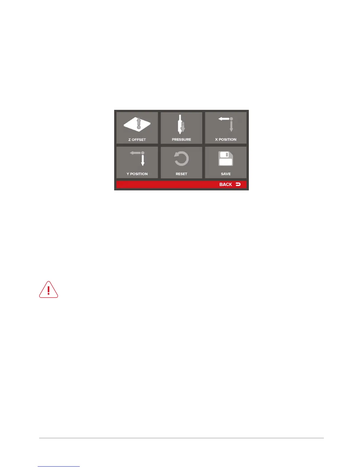
Autocompensation Settings – menu referring to printer autocompensation settings:
Z Offset – manual correction of the distance in Z axis. It allows for adding (or subtracting) a specied value to the measure-
ment point in Z axis (autocompensation). In practice, if Z offset is set to 0.1 mm, the print will be started higher by this value:
Height of the rst layer: 0.2 mm
0.2 mm + Z Offset: 0.1 mm = actual start height: 0.3 mm
The option can be useful when using adhesion bands or pads.
When using such a solution, Z-offset should be set to a value corresponding to the pad thickness. The parameter can
adopt negative values, then the print start point will be set lower (closer to the table).
CAUTION:
negative Z offset values can never exceed the rst layer thickness!
Pressure – sensitivity of the measurement point for the Z axis autocompensation. It allows for dening the value of head
pressure during height measurement. Sensitivity can be adjusted within the range from 20 (approx. 0.5 g) to 120 (approx.
4 g). In the case of easily owing materials it may be necessary to increase the measured pressure to reduce the risk of
head homing on the material outowing during material measurement. Otherwise, the print may start too high because
of taking into account the thickness of the material that has own under the head.
X Position – denes the distance between the autocompensation measure point and the homing base in X axis. By mod-
ifying this value it is possible to move the measure point in X axis.
Y Position – denes the distance between the autocompensation measure point and the homing base in axis Y. By mod-
ifying this value it is possible to move the measuring point along Y axis.
RESET – restores default values for this menu.
SAVE – saves all introduced changes to device memory.