Aprisa LTE User Manual 2.1
Front Panel Connections
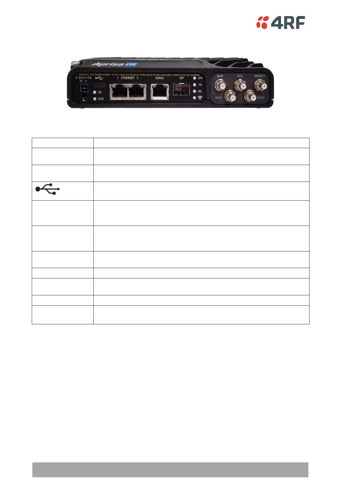
The front panel connections to the LTE are:
+9 to +32 VDC (negative ground) DC power input using pins 1 & 2 of the 4 pin
Molex Micro-Fit 3.0 connector. See ‘Power Supply’ on page 51.
General Purpose I/O with one input and one output using the power connector
pins 3 & 4 of the 4 pin Molex Micro-Fit 3.0 connector. See ‘GPIO’ on page 62.
USB Port using a USB type C connector.
Used for software upgrade. See ‘Software Upgrade’ on page 47.
Integrated 100Base-TX layer-3 Ethernet switch/router using RJ45 connectors.
Used for Ethernet user traffic and product management. See ‘Ethernet Interface
Connections’ on page 59.
One port of RS-232 / RS-422 / RS-485 serial using RJ45 connector.
See ‘Serial RS-232 Interface Connections’ on page 60 and ‘Serial RS-422 / RS-485
Interface Connections’ on page 61.
SFP module socket see ‘SFP Modules’ on page 41. The LTE router supplied with
dust plug fitted to SFP socket.
Main cellular LTE MIMO antenna using 50 ohm QMA female connector.
GNSS (Global Navigation Satellite System) antenna using 50 ohm QMA female
connector.
Diversity cellular LTE MIMO antenna using 50 ohm QMA female connector.
Wi-Fi 1 & Wi-Fi 2
(when Wi-Fi fitted)
For connection of Wi-Fi MU-MIMO antennas, see ‘Wi-Fi Antenna Requirements’
on page 57.