110 ACS550 User’s Manual
Parameters
5 = DI3U,4D(R) – Defines digital inputs as the speed reference source (motor potentiometer control).
• Digital input
DI3 increases the speed (the U stands for “up”).
• Digital input
DI4 decreases the speed (the D stands for “down”).
• A Stop command resets the reference to zero (the
R stands for “reset”).
• Parameter 2205
ACCELER TIME 2 controls the reference signal’s rate of change.
6 =
DI3U,4D – Same as above (DI3U,4D(R)), except:
• A Stop command does not reset the reference to zero. The reference is stored.
• When the drive restarts, the motor ramps up (at the selected acceleration rate) to the stored reference.
7 =
DI5U,6D – Same as above (DI3U,4D), except that DI5 and DI6 are the digital inputs used.
8 =
COMM – Defines the fieldbus as the reference source.
9 =
COMM+AI1 – Defines a fieldbus and analog input 1 (AI1) combination as the reference source. See Analog input
reference correction below.
10 =
COMM
*
AI1 – Defines a fieldbus and analog input 1 (AI1) combination as the reference source. See Analog input
reference correction below.
11 =
DI3U,4D(RNC) – Same as DI3U,4D(R) above, except that:
• Changing the control source (
EXT1 to EXT2, EXT2 to EXT1, LOC to REM) does not copy the reference.
12 =
DI3U,4D(NC) – Same as DI3U,4D above, except that:
• Changing the control source (
EXT1 to EXT2, EXT2 to EXT1, LOC to REM) does not copy the reference.
13 =
DI5U,6D(NC) – Same as DI5U,6D above, except that:
• Changing the control source (
EXT1 to EXT2, EXT2 to EXT1, LOC to REM) does not copy the reference.
14 =
AI1+AI2 – Defines an analog input 1 (AI1) and analog input 2 (AI2) combination as the reference source. See
Analog input reference correction below.
15 =
AI1
*
AI2 – Defines an analog input 1 (AI1) and analog input 2 (AI2) combination as the reference source. See
Analog input reference correction below.
16 =
AI1-AI2 – Defines an analog input 1 (AI1) and analog input 2 (AI2) combination as the reference source. See
Analog input reference correction below.
17 =
AI1/AI2 – Defines an analog input 1 (AI1) and analog input 2 (AI2) combination as the reference source. See
Analog input reference correction below.
20 =
KEYPAD(RNC) – Defines the control panel as the reference source.
• A Stop command resets the reference to zero (the
R stands for reset.).
• Changing the control source (
EXT1 to EXT2, EXT2 to EXT1) does not copy the reference.
21 =
KEYPAD(NC) – Defines the control panel as the reference source.
• A Stop command does not reset the reference to zero. The reference is stored.
• Changing the control source (
EXT1 to EXT2, EXT2 to EXT1) does not copy the reference.
Analog input reference correction
Parameter values 9, 10 and 14…17 use the formula in the following table.
Where:
• C = Main reference value
( =
COMM for values 9, 10 and
=
AI1 for values 14…17).
• B = Correcting reference
( =
AI1 for values 9, 10 and
=
AI2 for values 14…17).
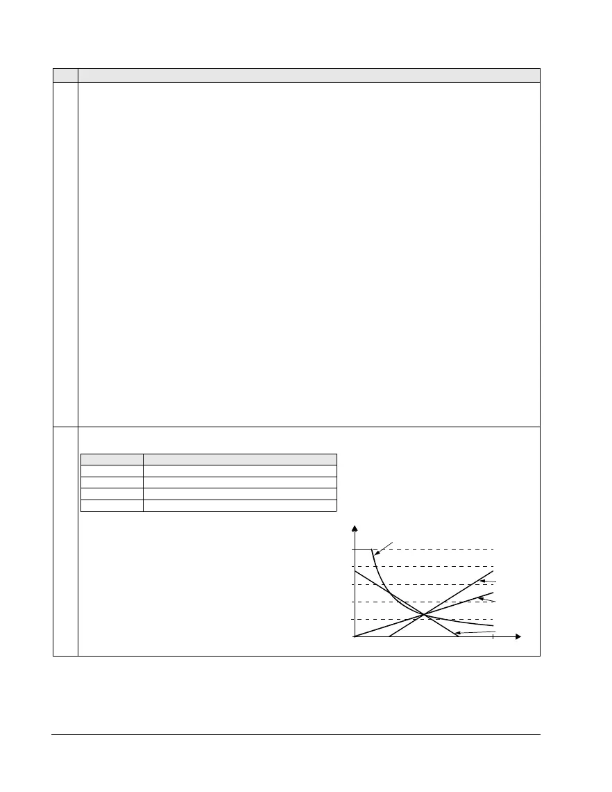
Example:
The figure shows the reference source curves for value
settings 9, 10 and 14…17, where:
• C = 25%.
• P 4012
SETPOINT MIN = 0.
• P 4013
SETPOINT MAX = 0.
• B varies along the horizontal axis.
Code Description
Value setting Calculation of the AI reference
C + B C value + (B value - 50% of reference value)
C
*
B C value · (B value / 50% of reference value)
C - B (C value + 50% of reference value) - B value
C / B (C value · 50% of reference value) / B value
120
100
80
60
40
20
0
0
100%
9, 14 (+)
16 (-)
10, 15 (
*
)
17 (/)
B