282 ACS550 User’s Manual
Technical data
Note: Never mix 24 V DC and 115/230 V AC signals in the same cable.
Analog cables
Recommendations for analog signal runs:
• Use double shielded, twisted pair cable.
• Use one individually shielded pair for each signal.
• Do not use a common return for different analog signals.
Digital cables
Recommendation for digital signal runs: A double shielded cable is the best
alternative, but single-shielded, twisted, multi-pair cable is also usable.
Control panel cable
If the control panel is connected to the drive with a cable, use only Category 5 Patch
ethernet cable. The maximum length that is tested to meet EMC specifications is 3 m
(9.8 ft). Longer cables are susceptible to electromagnetic noise and must be user-
tested to verify that EMC requirements are met. Where long runs are required
[especially for runs longer than about 12 m (40 ft)], use a RS232/RS485 converter at
each end and run RS485 cable.
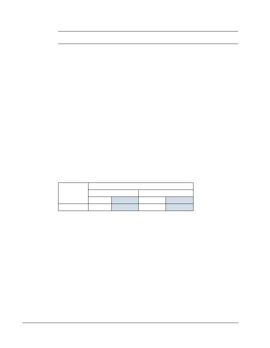
Drive’s control connection terminals
The following table provides specifications for the drive’s control terminals
Efficiency
Approximately 98% at nominal power level.
Frame size
Control
Maximum wire size
1
Torque
mm
2
AWG N·m lb-ft
All 1.5
16 0.4 0.3
1
Values given for solid wires.
For stranded wires, the maximum size is 1 mm
2
.