266 ACS550 User’s Manual
Technical data
Size wiring according to local safety regulations, appropriate input voltage and the
drive’s load current. In any case, the conductor must be less than the maximum limit
defined by the terminal size (see section Drive’s power connection terminals on page
268).
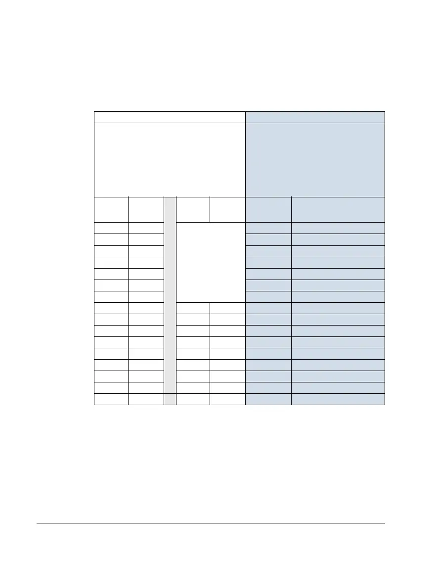
The table below lists copper and aluminium cable types for different load currents.
These recommendations apply only for the conditions listed at the top of the table.
Ground connections
For personnel safety, proper operation and reduction of electromagnetic emission/
pick-up, the drive and the motor must be grounded at the installation site.
• Conductors must be adequately sized as required by safety regulations.
• Power cable shields must be connected to the drive PE terminal in order to meet
safety regulations.
IEC NEC
Based on:
• EN 60204-1 and IEC 60364-5-2/2001
• PVC insulation
• 30 °C (86 °F) ambient temperature
• 70 °C (158 °F) surface temperature
• cables with concentric copper shield
• not more than nine cables laid on cable ladder
side by side.
Based on:
• NEC Table 310-16 for copper wires
• 90 °C (194 °F) wire insulation
• 40 °C (104 °F) ambient temperature
• not more than three current-carrying
conductors in raceway or cable, or earth
(directly buried)
• copper cables with concentric copper shield.
Max. load
current
A
Cu cable
mm
2
Max. load
current
A
Al cable
mm
2
Max. load
current
A
Cu wire size
AWG/kcmil
14 3×1.5 Aluminium cable
cannot be used with
frame sizes R1…R5
because of its lower
capacity.
22.8 14
20 3×2.5
27.3 12
27 3×4
36.4 10
34 3×6
50.1 8
47 3×10
68.3 6
62 3×16
86.5 4
79 3×25
100 3
98 3×35
91 3×50 118 2
119 3×50
117 3×70 137 1
153 3×70
143 3×95 155 1/0
186 3×95
165 3×120 178 2/0
215 3×120
191 3×150 205 3/0
249 3×150
218 3×185 237 4/0
284 3×185
257 3×240 264 250 MCM or 2 × 1
274 3× (3×50) 291 300 MCM or 2 × 1/0
285 2× (3×95) 319 350 MCM or 2 × 2/0