268 ACS550 User’s Manual
Technical data
IT systems
WARNING! Do not attempt to install or remove EM1, EM3, F1 or F2 screws while
power is applied to the drive’s input terminals.
For IT systems [an ungrounded power system or a high resistance-grounded (over
30 ohm) power system]:
• Disconnect the ground connection to the internal EMC filters:
– ACS550-01, frame sizes R1…R4: Remove both the EM1 and EM3 screws
(see section Power connection diagrams on page 20).
– ACS550-U1, frame sizes R1…R4: Remove the EM1 screw –
drive is shipped
with EM3 removed (see section Power connection diagrams on page 20).
– Frame sizes R5…R6: Remove both the F1 and F2 screws (see section Power
connection diagrams, page 21).
• Where EMC requirements exist, check for excessive emission propagated to
neighboring low voltage networks. In some cases, the natural suppression in
transformers and cables is sufficient. If in doubt, use a supply transformer with
static screening between the primary and secondary windings.
• Do NOT install an external RFI/EMC filter. Using an EMC filter grounds the input
power through the filter capacitors, which could be dangerous and could damage
the drive.
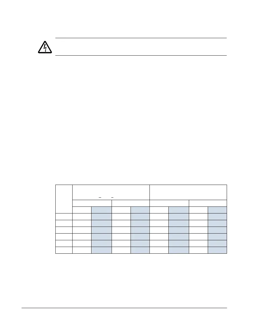
Drive’s power connection terminals
The following table provides specifications for the drive’s power connection
terminals.
Frame
size
U1, V1, W1
U2, V2, W2
BRK+
, UDC+ terminals
Earthing PE terminal
Max. terminal size Torque Max. terminal size Torque
mm
2
AWG N·m lb-ft mm
2
AWG N·m lb-ft
R1
1
6 81.41410 1.4 1
R2
1
10 61.411081.41
R3
1
25 31.81.3 16 61.81.3
R4
1
50 1/0 2 1.5 35 222
R5
1
70 2/0 15 11 70 2/0 15 11
R6 185
350 MCM 40 30 95 4/0 8 6
00467918.xls B
1
Aluminium cable cannot be used with frame sizes R1…R5 because of its lower capacity.