20 ACS550 User’s Manual
Installation
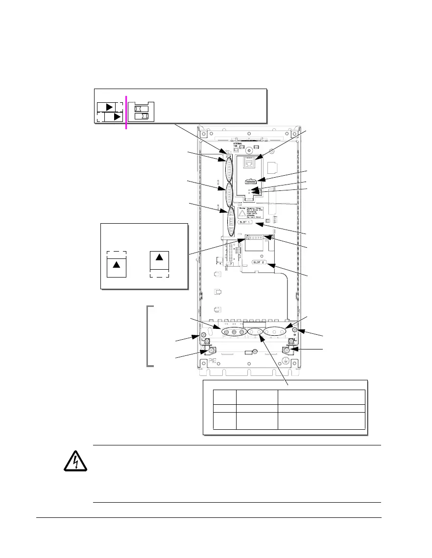
Power connection diagrams
The following diagram shows the terminal layout for frame size R3, which, in
general, applies to frame sizes R1
…R6, except for the R5/R6 power and ground
terminals.
WARNING! For IT systems and corner grounded TN systems, disconnect the
internal EMC filter by removing:
- On ACS550-01: screws EM1 and EM3
- On ACS550-U1: screw EM1 (drive is shipped with EM3 already removed).
See IT systems on page 268 and Corner grounded TN systems on page 267.
Panel connector
Fault LED (red)
Optional module 1
J2 – DIP switch
X1 – Communications
Optional module 2
GND
Power output to motor
Power input
EM1
X1 – Analog inputs and outputs
X1 – Digital inputs
X1 – Relay outputs
J2
ON
off position on position
for RS485 termination
(and 10 V ref. voltage output)
(and 24 V aux. voltage output)
PE
(U1, V1, W1)
(U2, V2, W2)
Optional braking
Frame
size
Terminal
labels
Brake options
R1, R2 BRK+, BRK- Brake resistor
R3, R4 UDC+, UDC- • Braking unit
• Chopper and resistor
(RS485)
R5/R6 differ.
See
Frame sizes
next page.
Diagram shows the R3 frame.
J2
ON
Other frames have similar layouts.
J1
AI1: (in voltage position)
AI2: (in current position)
ON
ON
J1 – DIP switches for analog inputs (two types can be used)
ON
12
J1
FlashDrop option
Power LED (green)
3AUA0000001571
EM3