ACS550 User’s Manual 21
Installation
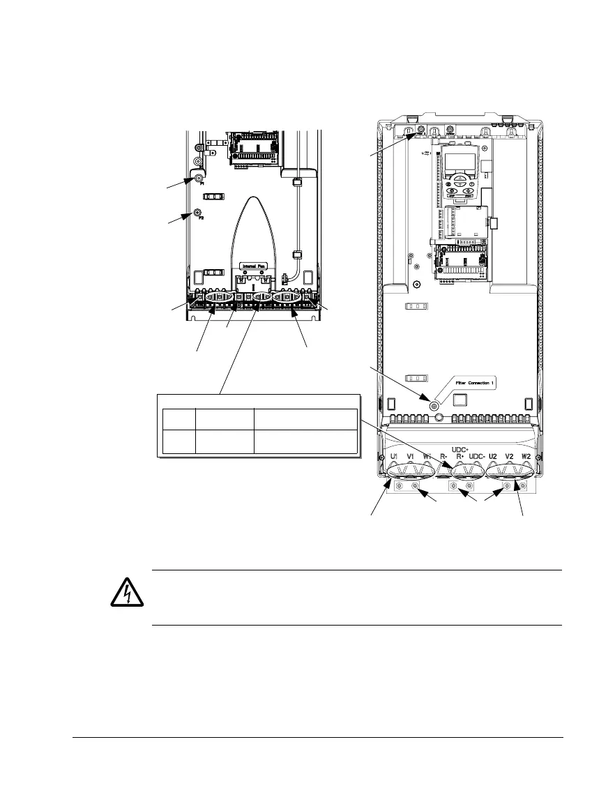
The following diagram shows the power and ground terminal layout for frame sizes
R5 and R6
WARNING! For IT systems and corner grounded TN systems, disconnect the
internal EMC filter by removing screws F1 and F2.
See IT systems on page 268 and Corner grounded TN systems on page 267.
GND
Power input
PE
(U1, V1, W1)
Optional braking
Frame
size
Terminal
labels
Brake options
R5, R6 UDC+, UDC- • Braking unit
• Chopper and resistor
X0011
F2
Power input
PE
(U1, V1, W1)
F1
F2
X0013
Power output to motor
(U2, V2, W2)
R5 R6
GND
GND
Power output to motor
(U2, V2, W2)
F1