ACS550 User’s Manual 281
Technical data
Control connections
Control connection specifications
Control cables
General recommendations
Use multi-core cables with a braided copper wire screen, temperature rated at 60 °C
(140 °F) or above:
At the drive end, twist the screen together into a bundle not longer than five times its
width and connected to terminal X1-1 (for digital and analog I/O cables) or to either
X1-28 or X1-32 (for RS485 cables). Leave the other end of the cable shield
unconnected.
Route control cables to minimize radiation to the cable:
• Route as far away as possible from the input power and motor cables [at least
20 cm (8 in)].
• Where control cables must cross power cables, make sure they are at an angle
as near 90° as possible.
• Stay at least 20 cm (8 in) from the sides of the drive.
Use care in mixing signal types on the same cable:
• Do not mix relay-controlled signals using more than 30 V and other control
signals in the same cable.
• Run relay-controlled signals as twisted pairs (especially if voltage > 48 V). Relay-
controlled signals using less than 48 V can be run in the same cables as digital
input signals.
Control connection specifications
Analog inputs and
outputs
See section Control terminals table on page 22.
Digital inputs
Digital input impedance 1.5 kohm. Maximum voltage for digital inputs is
30 V.
Relays
(digital outputs)
• Max. contact voltage: 30 V DC, 250 V AC
• Max. contact current / power: 6 A, 30 V DC; 1500 VA, 250 V AC
• Max. continuous current: 2 A rms (cos ϕ = 1), 1 A rms (cos ϕ =0.4)
• Minimum load: 500 mW (12 V, 10 mA)
• Contact material: Silver-nickel (AgN)
• Isolation between relay digital outputs, test voltage: 2.5 kV rms, 1 minute
Cable specifications See section Control terminals table on page 22.
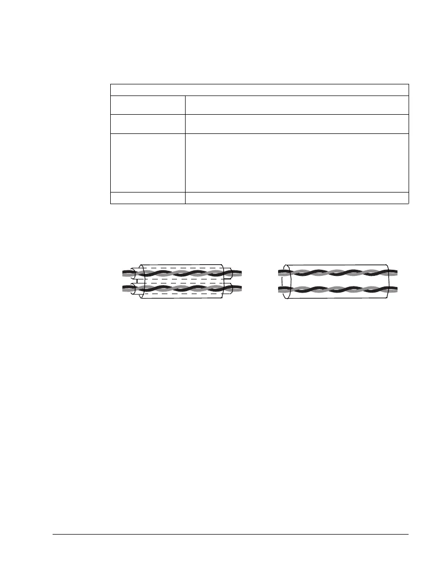
Double shielded
Single shielded
Example: JAMAK by Draka NK Cables
Example: NOMAK by Draka NK Cables