14 ACS550 User’s Manual
Installation
Motor compatibility
The motor, drive and supply power must be compatible:
Tools required
To install the ACS550 you need the following:
• screwdrivers (as appropriate for the mounting hardware used)
• wire stripper
• tape measure
• drill
• for installations involving ACS550-U1, frame sizes R5 or R6 and IP54 / UL type
12 enclosures: punch for creating conduit mounting holes
• for installations involving ACS550-U1, frame size R6: appropriate crimping tool
for power cable lugs. See section Power terminal considerations – R6 frame size
on page 269.
• mounting hardware: screws or nuts and bolts, four each. The type of hardware
depends on the mounting surface and the frame size:
Suitable environment and enclosure
Confirm that the site meets the environmental requirements. To prevent damage
prior to installation, store and transport the drive according to the environmental
requirements specified for storage and transportation. See section Ambient
conditions
on page 289.
Motor
specification
Verify Reference
Motor type 3-phase induction motor –
Nominal current Motor value is within this
range: 0.2…2.0 · I
2hd
(I
2hd
= drive heavy duty
current)
• Type code label on drive, entry for Output I
2hd
,
or
• Type code on drive and rating table in chapter
Technical data on page 259.
Nominal frequency 10…500 Hz –
Voltage range Motor is compatible with
the ACS550 voltage range.
208…240 V (for ACS550-X1-XXXX-2) or
380…480 V (for ACS550-X1-XXXX-4) or
500…600 V (for ACS550-U1-XXXX-6)
Insulation 500…600 V drives: Either
the motor complies with
NEMA MG1 Part 31, or a
du/dt filter is used between
the motor and drive.
For ACS550-U1-XXXX-6
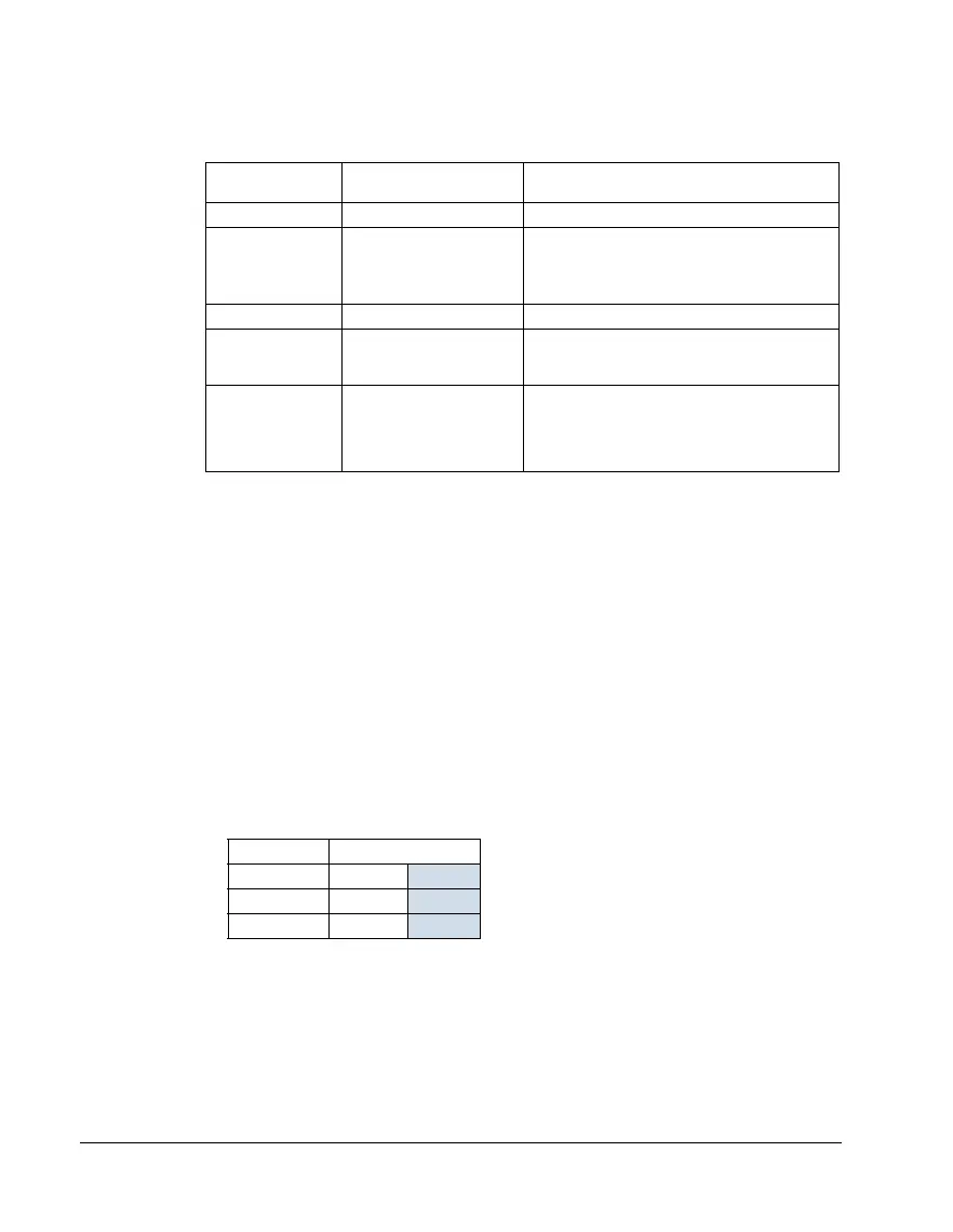
Frame size Mounting hardware
R1…R4 M5
#10
R5 M6
1/4 in
R6 M8
5/16 in