ACS550 User’s Manual 267
Technical data
• Power cable shields are suitable for use as equipment grounding conductors only
when the shield conductors are adequately sized as required by safety
regulations.
• In multiple drive installations, do not connect drive terminals in series.
Corner grounded TN systems
WARNING! Do not attempt to install or remove EM1, EM3, F1 or F2 screws while
power is applied to the drive’s input terminals.
Corner grounded TN systems are defined in the following table. In such systems,
disconnect the internal ground connection by removing the screws (do this also if the
grounding configuration of the system is unknown):
• ACS550-01, frame sizes R1…R4: Remove both the EM1 and EM3 screws (see
section Power connection diagrams on page 20).
• ACS550-U1, frame sizes R1…R4: Remove the EM1 screw –
drive is shipped with
EM3 removed (see section Power connection diagrams on page 20).
• Frame sizes R5…R6: Remove both the F1 and F2 screws (see section Power
connection diagrams, page 21).
The screws (M4×16) make an internal ground connection that
reduces electro-magnetic emission. Where EMC (electro-
magnetic compatibility) is a concern, and the system is
symmetrically grounded, the screws may be installed. For
reference, the diagram on the right illustrates a symmetrically
grounded TN system.
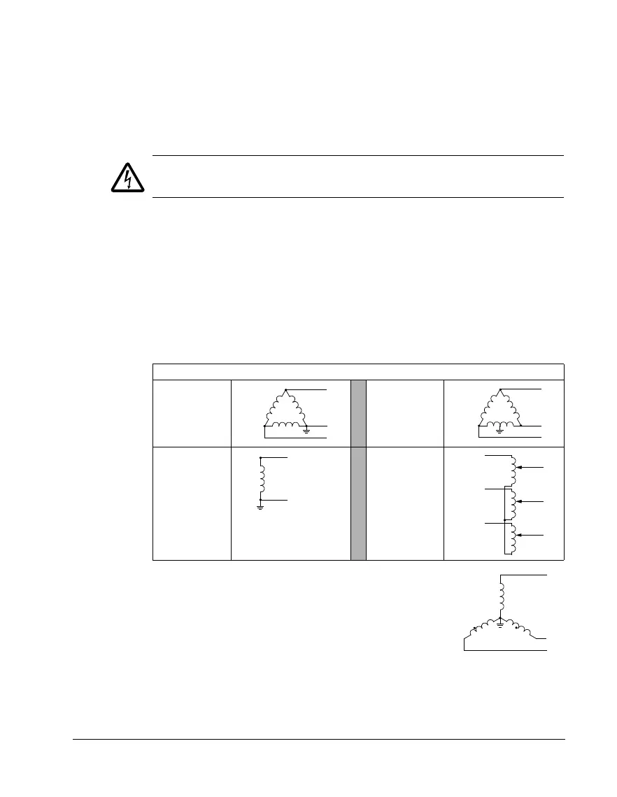
Corner grounded TN systems – EM1, EM3, F1 and F2 must be out
Grounded at the
corner of the
delta
Grounded at the
mid point of a
delta leg
Single phase,
grounded at an
end point
Three phase
“Variac” without
solidly grounded
neutral
L1
L2
L3
L1
L2
L3
L1
N
L1
L1
L2
L2
L3
L3
L1
L2
L3