ACS550 User’s Manual 151
Parameters
For other faults, or for anticipating motor overheating using a model, see Group 30:
FAULT FUNCTIONS.
Code Description
3501 SENSOR TYPE
Identifies the type of motor temperature sensor used, PT100 (°C), PTC (ohm) or thermistor.
See parameters 1501
AO1 CONTENT SEL and 1507 AO2 CONTENT SEL.
0 =
NONE
1 = 1 x PT100 – Sensor configuration uses one PT 100 sensor.
• Analog output
AO1 or AO2 feeds constant current through the sensor.
• The sensor resistance increases as the motor temperature rises, as does the voltage over the sensor.
• The temperature measurement function reads the voltage through analog input
AI1 or AI2 and converts it to
degrees Celsius.
2 = 2 x PT100 – Sensor configuration uses two PT100 sensors.
• Operation is the same as for above 1 x PT100.
3 = 3 x PT100 – Sensor configuration uses three PT100 sensors.
• Operation is the same as for above 1 x PT100.
4 =
PTC – Sensor configuration uses PTC.
• The analog output feeds a constant current through the sensor.
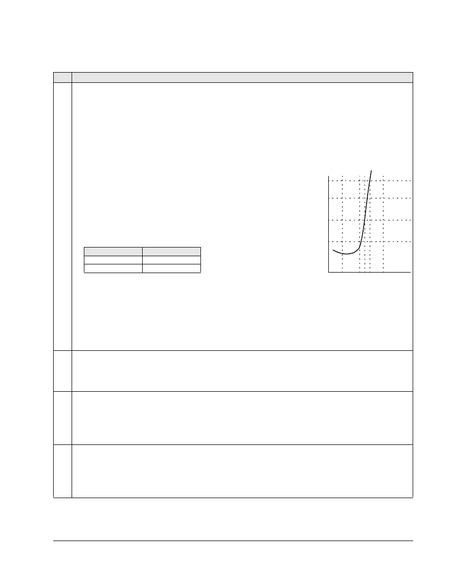
• The resistance of the sensor increases sharply as the motor
temperature rises over the PTC reference temperature (T
ref
), as does
the voltage over the resistor. The temperature measurement function
reads the voltage through analog input
AI1 and converts it into ohms.
• The figure shows typical PTC sensor resistance values as a function of
the motor operating temperature.
5 =
THERM(0) – Sensor configuration uses a thermistor.
• Motor thermal protection is activated through a digital input. Connect either a PTC sensor or a normally closed
thermistor relay to a digital input. The drive reads the digital input states as shown in the above table.
• When the digital input is ‘0’ the motor is overheated.
• See the figures in the introduction to this group.
6 =
THERM(1) – Sensor configuration uses a thermistor.
• Motor thermal protection is activated through a digital input. Connect a normally open thermistor relay to a digital
input. The drive reads the digital input states as shown in the table above.
• When the digital input is ‘1’ the motor is overheated.
• See the figures in the introduction to this group.
3502 INPUT SELECTION
Defines the input used for the temperature sensor.
1 =
AI1 – PT100 and PTC.
2 =
AI2 – PT100 and PTC.
3…8 =
DI1…DI6 – Thermistor
3503 ALARM LIMIT
Defines the alarm limit for motor temperature measurement.
• At motor temperatures above this limit, the drive displays an alarm (2010, MOTOR TEMP)
For thermistors:
0 – de-activated
1 – activated
3504 FAULT LIMIT
Defines the fault limit for motor temperature measurement.
• At motor temperatures above this limit, the drive displays a fault (9,
MOT OVERTEMP) and stops the drive.
For thermistors:
0 – de-activated
1 – activated
100
550
1330
4000
ohm
T
Temperature Resistance
Normal < 3 kohm
Excessive > 28 kohm