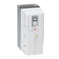
Frame
size
NoiseAir flow
Thermal losses
1)
Drive
type
ACS560-
Main circuit
and control
circuit Max.
load
Control
circuit
Max. load
Control
circuit
Min. load
Main cir-
cuit nom-
inal
I
1N
,
I
N
dB(A)m
3
/hWWWW
3 phases
U
N
= 400V (380…480V)
R063.10574490.33502A6-4
R063.10575190.34203A3-4
R063.10575990.35004A0-4
R063.10577790.36805A6-4
R063.10579790.38807A2-4
R063.105712490.311509A4-4
R158.806316790.315812A6-4
R265.8012821790.3208017A-4
R265.8012833190.3322025A-4
R370116430253.5405033A-4
R370116525253.5500039A-4
R370116619253.5594046A-4
R462280835253.5810062A-4
R4622801024253.5999073A-4
R5622801240253.51215088A-4
R5674351510253.51485106A-4
R6674351476364.11440145A-4
R7674501976364.11940169A-4
R7675502346364.12310206A-4
R8655503336364.13300246A-4
R86511503936364.13900293A-4
1)
The table shows the typical drive losses when it operates at 90% of the nominal output frequency and
100% of the nominal output current. See also Energy efficiency data (ecodesign) (page 159).
Terminal and lead-through data for the power cables
Input, motor, resistor and DC cable lead-throughs, maximum wire sizes (per phase)
and terminal screw sizes and tightening torques (
T
) are given below.
150 Technical data

 Loading...