124 Control macros
Terminal sizes
• (frames R0…R8): 0.14…1.5 mm
2
(all terminals)
• Tightening torques: 0.5…0.6 N·m (0.4 lbf·ft)
Notes
1)
Current [0(4)…20 mA, R
in
< 500 ohm] or voltage [ 0(2)…10 V, R
in
> 200 kohm]
input as selected with parameter 12.15 AI1 unit selection.
2)
Current [0(4)…20 mA, R
in
= 100 ohm] or voltage [ 0(2)…10 V, R
in
> 200 kohm]
input as selected with parameter 12.25 AI2 unit selection.
3)
Total load capacity of the auxiliary voltage output +24V (X2:10) = 6.0 W (250 mA /
24 V). User can use this source for either of the I/O connections (DI1... DI2- RO1 or
DI3...DI6 - RO2~RO3).
4)
Connected with jumpers at the factory.
5)
Ground the outer shield of the cable 360 degrees under the grounding clamp on
the grounding shelf for the control cables.
6)
Can be used to set up pressure alarm warning.
7)
Can be used for cold start prevention with connection to ‘temperature reached’
output of temperature controller or PLC
8)
Input signal
9)
Output signal
10)
For R0...R2 frames only
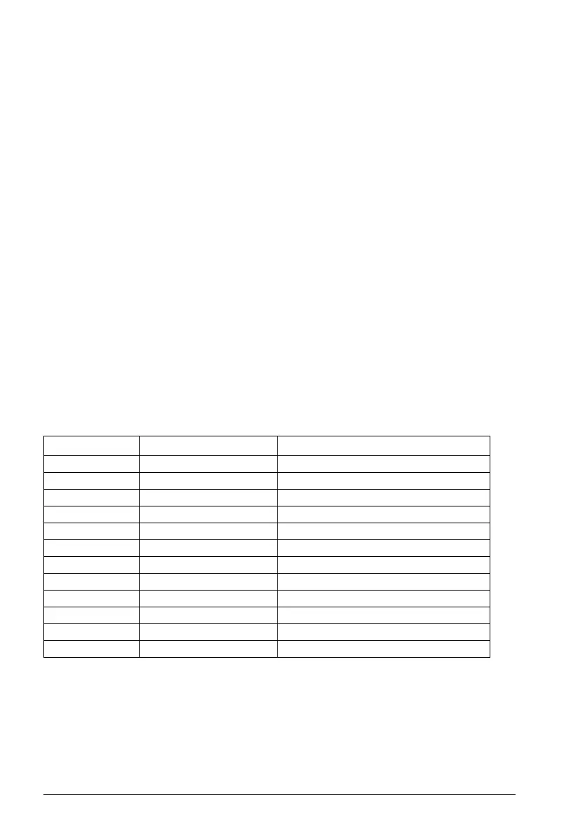
In addition, some inputs and settings are set automatically as follows:
For information on cable connection and drive operation, see Control Connections in
the Hardware manual (3AXD50000044998)
No. Name (Input/Setting) Value
19.11 Ext1/Ext2 selection 5 = DI3
19.14 Ext2 control mode 3 = Torque
20.02 Ext1 start trigger type 1 = Level
20.06 Ext2 commands 2 = In1 Start; In2 Dir
20.07 Ext2 start trigger type 1 = Level
20.08 Ext2 in1 source 2 = DI1
20.09 Ext2 in2 source 2 = DI2
20.12 Run enable 1 source 7 = DI6
22.22 Constant speed sel1 5 = DI4
23.11 Ramp set selection 0 = DI5
26.11 Torque ref1 source 2 = AI2 scaled
31.11 Fault reset selection 0 = Not used