148 Safety functions
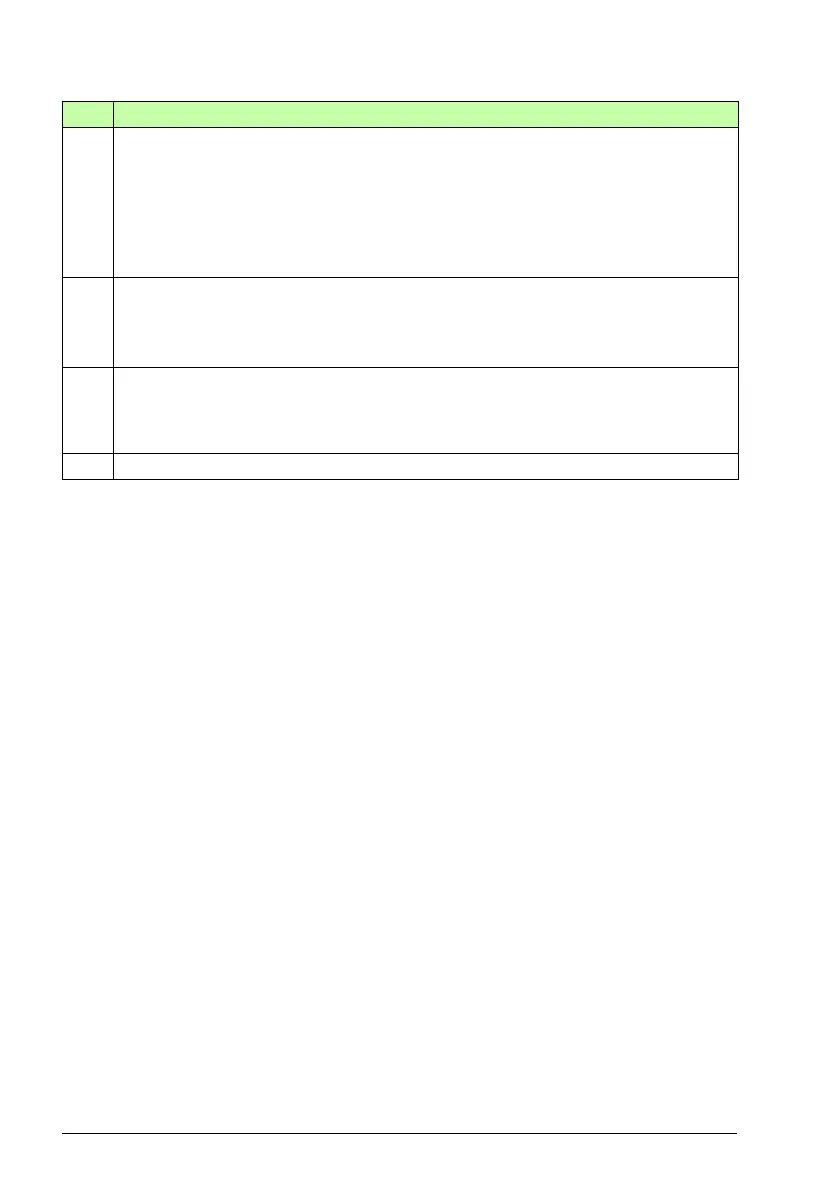
Step Description
1 The SLS request is received. The motor speed is above the SLS trip limit positive (A).
The drive starts to ramp down the motor speed. The SAR1 parameter 200.112 defines
the deceleration ramp slope until the speed reaches the SLS limit. The FSO starts the
SAR1 ramp monitoring (parameters SARx.21, SARx.22). SAR1 configuration defines
the target and monitoring limits for the deceleration ramp (SARx.22, 200.112,
SARx.02).
Note: If parameter 200.112 has value 0, the drive (parameter 23.23) defines the ramp.
2 The drive trips on a fault, there is a drive power loss, or user stops the drive by coast
stop. SAR1 monitoring of the FSO is switched off. SLS Modoff delay time starts
(parameters SLSx.05 & SLSx.06). STO.14 delay starts.
Note: This reaction is the default for FSO and the delay time is set to 0 ms.
3 Modulation of the drive has not returned and the SLSx.06 Modoff delay time has run
out, and FSO activates STO function and STO indication (parameter STO.21 STO
output). See section Safe torque off (STO) on page 67 for more information on how to
configure the STO function.
4 If modulation does not return, and STO.14 delay has elapsed, SLS indication goes on.