332 Configuration
Example 2 (with an encoder): The figure below shows an example of a simple STO
function set-up when an encoder is used. Configure the safety encoder interface first
(see section Configuring the safety encoder interface on page 313).
• redundant emergency stop button connected to input
(STO.11 STO input A = DI X113:1 & X114:1)
• automatic acknowledgement (STO.02 STO acknowledgement = Automatic)
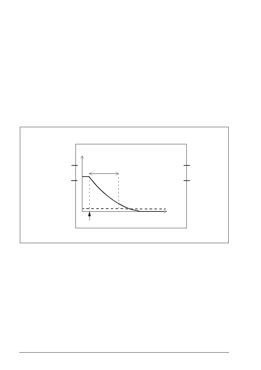
• zero speed limit where STO function is completed and it can be acknowledged is
40 rpm (parameter FSOGEN.52 Zero speed with encoder = 40 rpm)
• the fly-start feature is in use, that is, you can restart the drive before the motor has
stopped (STO.13 Restart delay after STO = 1000 ms)
• no output connected
• no brake (SBC.11 STO SBC usage = None).
STO.11
= DI X113:1 & X114:1
STO.12
= None
STO.21
= None
SBC.11 = None
STO.13 = 1000 ms
STO.02 = Automatic
STO activated
Time
STO.22
= None
Speed
Inputs
Outputs
FSOGEN.52
= 40 rpm