378 Configuration
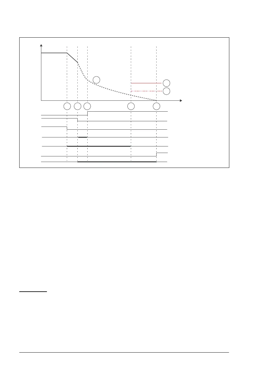
1. SLS request is activated (SLSx.11 SLS1 input A = DI X113:2 & X114:2). SLS time
delay monitoring is started (SLSx.04 SLS time delay = 2000 ms). Deceleration to
SLS limit speed is started (23.13 Deceleration time 1).
2. Modulation is lost. Motor starts to coast to a stop. SLS time monitoring limit is kept
active also when modulation is lost (SLSx.04 SLS time delay = 2000 ms). Modoff
delay time starts to run (SLSx.06 SLS ramp modoff delay time = 200 ms).
3. Modulation of the drive has not returned before the SLS ramp modoff delay time
has elapsed (SLSx.06 SLS ramp modoff delay time = 200 ms). FSO activates
SSE function (SSE.13 SSE function) as the modulation is lost. SSE function
triggers STO function regardless of the configuration of the SSE function. STO
indication goes on (STO.21 STO output = DO X113:7).
4. SLS time monitoring limit (SLSx.04 SLS time delay = 2000 ms).
5. STO.14 delay starts when drive modulation is lost. If modulation does not return,
SLS indication goes on after STO.14 delay has elapsed.
Example 2
: The figure below shows an example of the modoff situation with SLS
function with time monitoring when "Monitoring active" (parameter SLSx.05) is
selected:
• Basic parametrization of the SLS function made according to chapter Configuring
SLS on page 362.
• Monitoring active when drive modulation is lost (SLSx.05 SLS ramp modoff
reaction = Monitoring active)
SLS indication
Motor speed
Time
1 4 532
STO active
Drive modulation
SLS request
SLSx.06 Modoff time
delay monitoring
SLSx.04 time
delay monitoring
C
D
B
STO.14 delay
SLSx.06 SLSx.04