USER MANUAL | ICOS | INSTRUCTIONS | UM/ICOS-EN REV. B.2
Data Interface Connection Ports
This section describes the data interface connections for the GLA351-N2OCM and the
GLA351-N2OM1. These connections vary from analyzer to analyzer depending on the
ordered configuration.
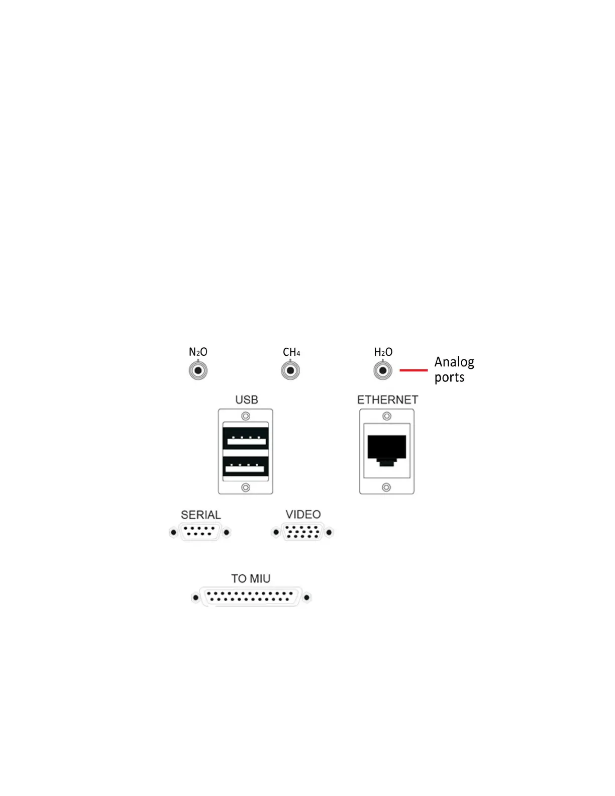
Analog ports – Provides a DC voltage proportional to the measured gas
concentration. If these outputs are connected to an external device, it must be
terminated into a moderate to high impedance (>1 kOhm).
USB ports – Used for transferring data to a USB memory device, or to connect a
USB keyboard and mouse.
Ethernet port – Connects the analyzer to a local area network (LAN) and allows
access to the data directory using an external computer.
Serial port (9 pin D-sub) – For real-time digital measurement output.
Video port (15 pin D-sub) – Connects an external monitor to the analyzer.
TO MIU port (25-pin data port) – For connecting to a Multiport Inlet Unit (optional).
DCS port (BNC male port) – Used to control the optional External Dynamic Dilution
System (EDDS). (Applicable for the GLA351-CCIA3)
Figure 5 shows an example of the
Data Interface Connection Ports
of a GLA351-N2OCM.
Figure 5: Data Interface Connection Ports (GLA351-N2OCM)

 Loading...


