USER MANUAL | ICOS | INSTRUCTIONS | UM/ICOS-EN REV. B.2
Gas Inlet/Outlet Connections
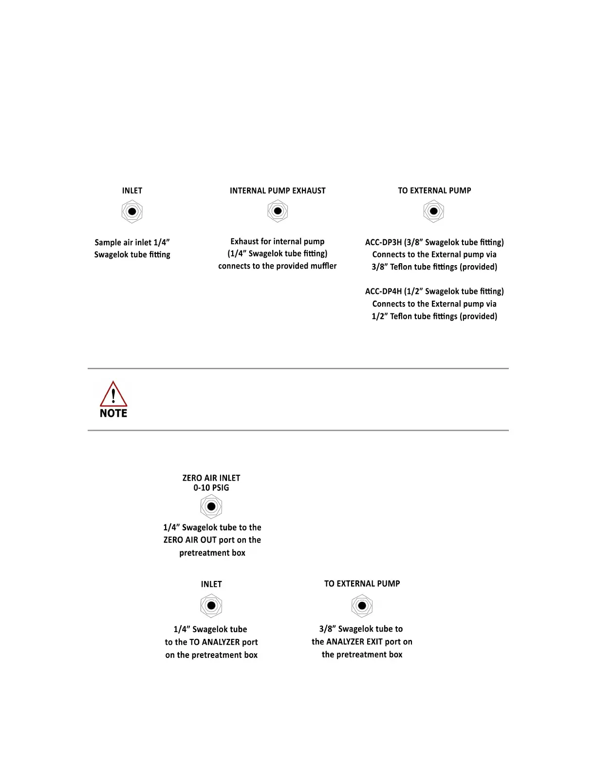
The gas inlet and outlet ports are located on the back panel of the analyzer. (Figure 3)
Configurations will vary among analyzer types. These ports are shown in detail in Figure 10.
The unit ships with inlets and outlets capped for protection. The connections use
Swagelok fittings ISO thread size 1/4”, 3/8” and ½”.
Figure 10: Gas Inlet/Outlets
For standard use with the internal pump, the optional TO EXTERNAL PUMP
port must remain capped with the provided cap.
Figure 11 shows the configuration for the GLA351-CCIA3 analyzer. The gas inlet and outlet
ports are located on the back panel of the analyzer. (Figure 3)
Figure 11: Gas Inlet/Outlets

 Loading...


