USER MANUAL | ICOS | INSTRUCTIONS | UM/ICOS-EN REV. B.2
Plumbing Diagram with a Pretreatment Box
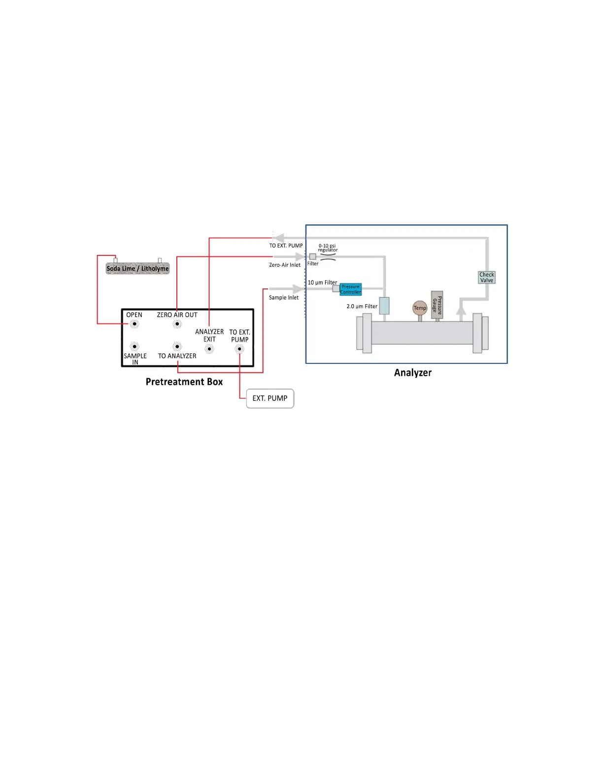
For the GLA351-CCIA3, the external pump draws gas through the
SAMPLE INLET
port (1/4”
Swagelok) on the back panel of the analyzer. The gas is filtered through a 10µm filter
before entering the pressure controller, which throttles the flow to maintain the optical cell
at its’ target pressure. The gas is exhausted through the
TO EXT. PUMP
port (3/8”
Swagelok).
Figure 6 shows the plumbing diagram for the GLA351-CCIA3.
Figure 9: Plumbing Diagram (GLA351-CCIA3)

 Loading...


