USER MANUAL | ICOS | INSTRUCTIONS | UM/ICOS-EN REV. B.2
3 Analyzer Setup
Connect the Power Cords
1. Connect the analyzer power cord from the AC power port on the back panel to a
grounded outlet of your power supply. (Figure 4)
2. If applicable, (for optional Fast-Flow mode), connect the external pump’s power
cord from the pump to the EXT. PUMP POWER port on the back panel of the
analyzer. (Figure 4)
Connect the Data Interface Connections
1. See Figure 5 for a detailed description of the connections.
Connect the Inlet/Outlet Plumbing Connections
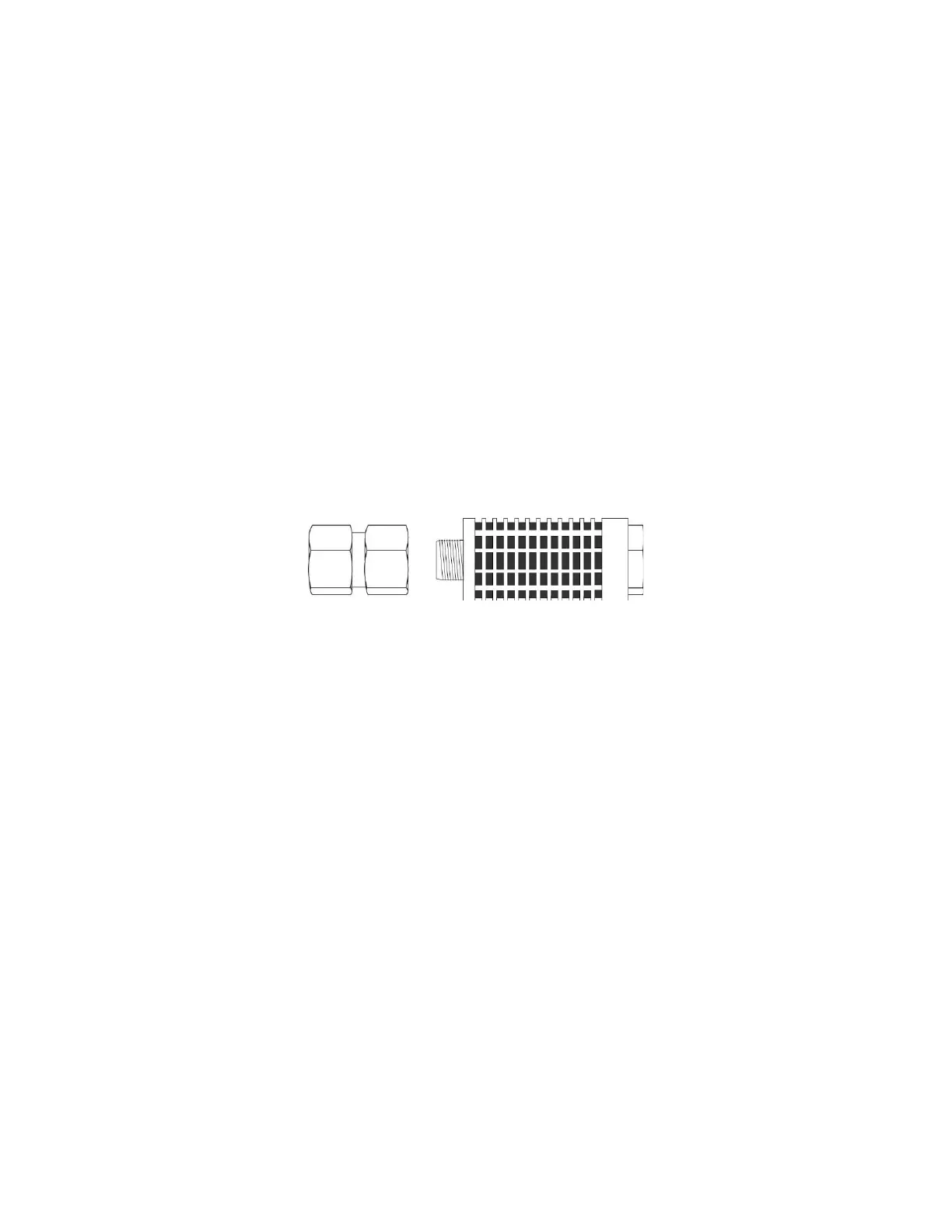
1. Connect the provided exhaust muffler with Swagelok adaptor to the INTERNAL
PUMP EXHAUST port to exhaust into the room air, or route to your facility
ventilation system, using ¼” tubing. (Figure 15)
Figure 15: Exhaust Muffler with ¼’ Swagelok Adaptor
2. If applicable, connect a ¼” sample tube (not provided) from the INLET port on the
back panel of the analyzer to your sample source.
3. If applicable, (for optional Fast-Flow mode), connect the External Pump’s 6’x 3/8”
Teflon tubing with Swagelok fittings from the external pump to the TO EXT PUMP
port on the back panel of the analyzer. (Figure 4)
a. Cap the Internal Pump Exhaust port with the provided ¼” Swagelok cap
during Fast-Flow operation. (Figure 10)

 Loading...


