USER MANUAL | ICOS | INSTRUCTIONS | UM/ICOS-EN REV. B.2
Plumbing Diagram
The plumbing diagram measures the internal flow of gas through the analyzers.
Standard Plumbing
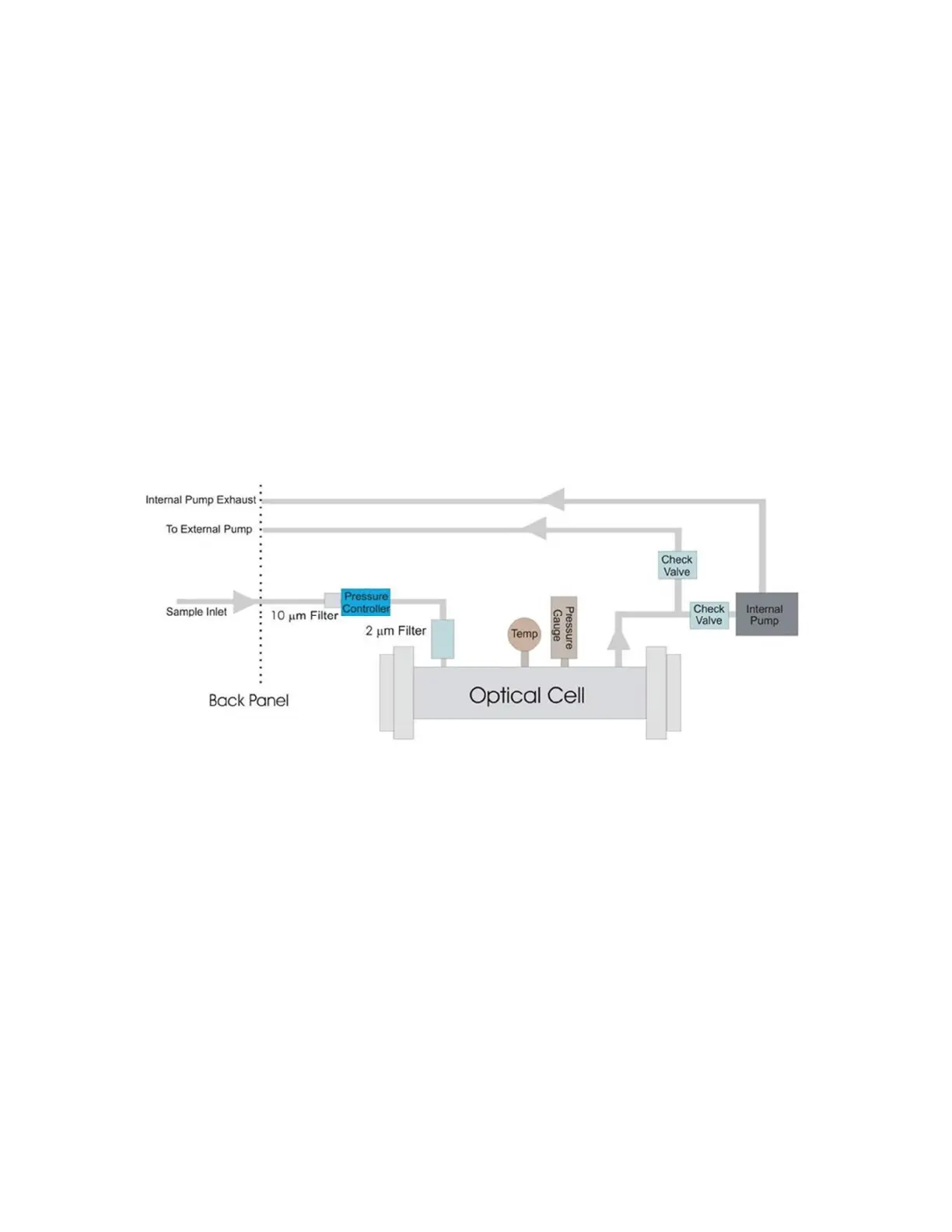
Figure 6 shows an example of the internal flow of gas in standard plumbing analyzers.
Configurations will vary depending on the analyzer type and may not include an external
pump.
For standard operation, the internal pump draws gas through the
Sample Inlet
Swagelok
port on the back panel of the analyzer. The gas is filtered through a filter before entering
the pressure controller, which determines the analyzer flow rate. The gas then travels
through the optical cell and is exhausted through the Internal Pump Exhaust port. The
acceptable inlet gas pressure range is 1 to 5 psig.
Figure 6: Standard Plumbing Diagram for a GLA351-N2OCM

 Loading...


