MN1941WEN Input / Output 4-15
4.3.4 Stepper control outputs - models NXE100-16xxSx
The stepper control outputs are available on connectors X2 and X3, as shown in section
4.1.1. There are four sets of stepper motor control outputs, operating in the range 60 Hz to
500 kHz. Each of the step (pulse) and direction signals from the NextMove e100 is driven by
a ULN2803 open collector Darlington output device. The STEPPERDELAY keyword allows a 0
- 4.25 µs delay to be introduced between state changes of the step and direction outputs.
The FREQ keyword can be used to directly control the output frequency, between 60 Hz and
500 kHz. Values less than 60 Hz will produce no output - see the Mint help file.
The ULN2003 drivers are static sensitive devices. Take appropriate ESD
precautions when handling the NextMove e100. A 5 V supply is provided on
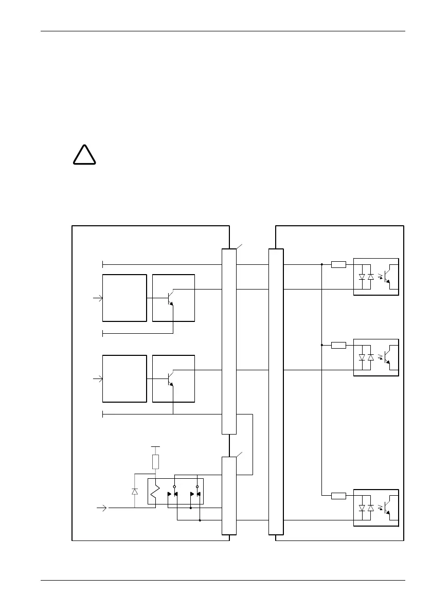
connectors X2 and X3 for powering external circuits, as shown in Figure 19. The
same 5 V supply is also present on connectors X5, X6 and X7 for powering
encoders. Ensure that the total combined current demand of all 5 V outputs does
not exceed 600 mA. It is usually necessary to connect a 470 Ω pull-up resistor
between the output and the 5 V supply (pin 4), especially where induced noise is
affecting a step or direction output.
Figure 19: Connections to a typical stepper drive (e.g. ABB DSM series)
ULN2803
74AHCT244
3
4
ULN2803
74AHCT244
5
7
‘X2’
‘X12’
+5 V
1
8
NextMove e100
Stepper drive opto-isolated inputs
Optocoupler
reference
Step clock
Input
CW/CCW
direction
input
Enable input
Direction
output
Step
output
GND
GND
+5V
+5V
Step0
DIR0
DGND
REL COM
REL NC
Enable