MN1941WEN Input / Output 4-31
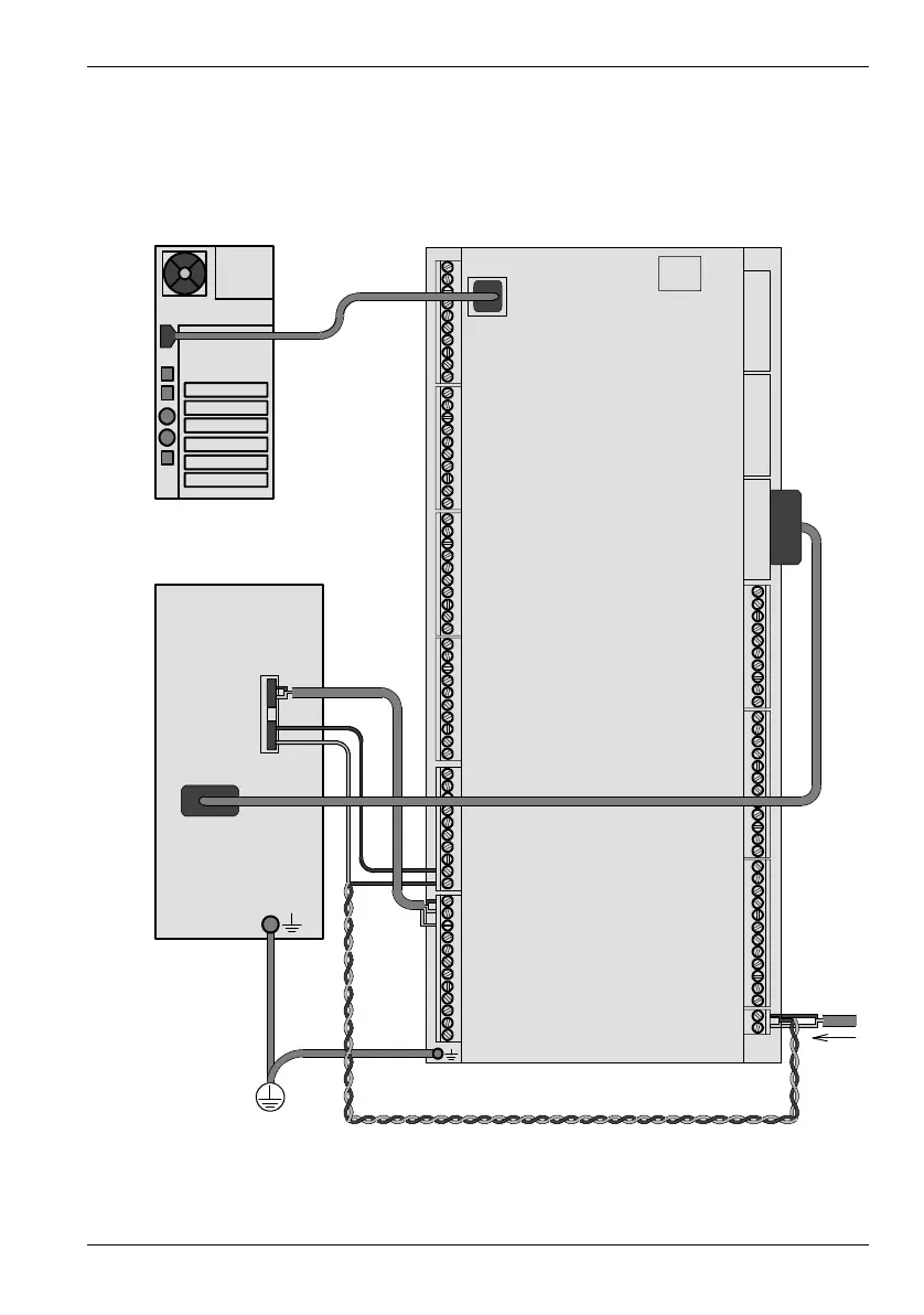
4.8 Connection summary - minimum wiring (local axis)
As a guide, Figure 31 shows an example of the typical minimum wiring required to allow the
NextMove e100 and a single axis servo amplifier to work together. Details of the connector
pins are shown in Table 2.
Figure 31: Example minimum system wiring
+24V
0V
X13
X5
X1
1
2
3
9
10
X12
USB
Host PC
NextMove e100
Servo amplifier
(axis 0)
Common earth/
ground
+24 V
control
supply
Demand+
Demand-
Enable
Gnd
Encoder output from
drive (or motor)
USB connection