4-16 Input / Output MN1941WEN
4.4 Other I/O
4.4.1 Encoder inputs 0-2
Three incremental encoders may be connected to NextMove e100, each with
complementary A, B and Z channel inputs. Each input channel uses a MAX3095 differential
line receiver with pull up resistors and terminators. Encoders must provide RS422 differential
signals. The use of individually shielded twisted pair cable is recommended. A 5 V supply is
provided on connectors X5, X6 and X7 for powering the encoders. On models NXE100-
16xxSx, the same 5 V supply is also present on connectors X2 and X3 for powering external
circuits (see section 4.3.4). Ensure that the total combined current demand of all 5 V outputs
does not exceed 600 mA. If the total current exceeds 1 A a self-resetting fuse will operate,
which may take a few minutes to reset.
4.4.1.1 Encoder input frequency
The maximum encoder input frequency is affected by the length of the encoder cables.
The theoretical maximum frequency is 20 million quadrature counts per second. This is
equivalent to a maximum frequency for the A and B signals of 5 MHz. However, the effect of
cable length is shown in Table 1:
The maximum recommended cable length is 30.5 m (100 ft).
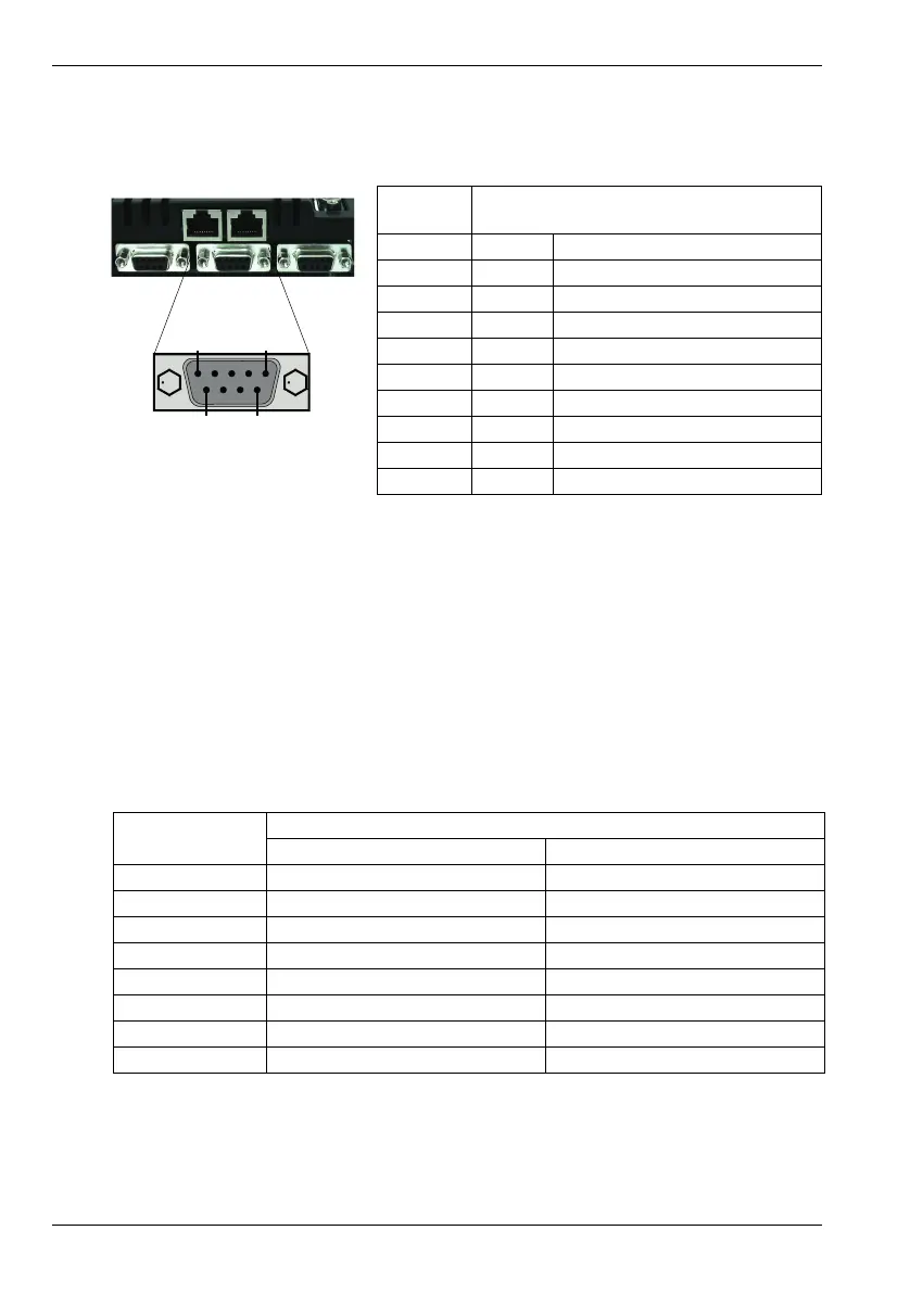
Location X5, X6, X7
Mating connectors: 9-pin male D-type
Pin Name Description
1 CHA+ Channel A signal
2 CHB+ Channel B signal
3 CHZ+ Index channel signal
4 Shield Shield connection
5 DGND Digital ground
6 CHA- Channel A signal complement
7 CHB- Channel B signal complement
8 CHZ- Index channel signal complement
9 +5V out Power supply to encoder
A and B signal
frequency
Maximum cable length
meters feet
1.3 MHz 26.56
500 kHz 10 32.8
250 kHz 20 65.6
100 kHz 50 164.0
50 kHz 100 328.1
20 kHz 300 984.2
10 kHz 700 2296.6
7kHz 1000 3280.8
Table 1: Effect of cable length on maximum encoder frequency