4-28 Input / Output MN1941WEN
4.7 CAN interface
The CAN bus is a serial based network originally developed for automotive applications, but
now used for a wide range of industrial applications. It offers low-cost serial communications
with very high reliability in an industrial environment; the probability of an undetected error is
4.7x10
-11
. It is optimized for the transmission of small data packets and therefore offers fast
update of I/O devices (peripheral devices) connected to the bus.
The CAN protocol only defines the physical attributes of the network, i.e. the electrical,
mechanical, functional and procedural parameters of the physical connection between
devices. The higher level network functionality on NextMove e100 is defined by the
CANopen protocol, one of the most used standards for machine control.
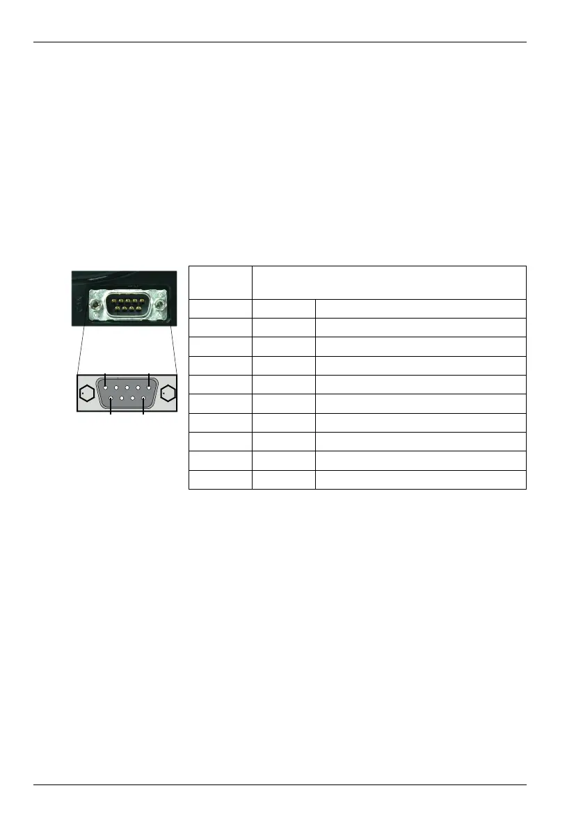
4.7.1 CAN connector
4.7.2 CAN wiring
A very low error bit rate over CAN can only be achieved with a suitable wiring scheme, so the
following points should be observed:
The two-wire data bus line may be routed parallel, twisted and/or shielded, depending on
EMC requirements. ABB recommends a twisted pair cable with the shield/screen
connected to the connector backshell, in order to reduce RF emissions and provide
immunity to conducted interference.
The bus must be terminated at both ends only (not at intermediate points) with resistors
of a nominal value of 120 Ω. This is to reduce reflections of the electrical signals on the
bus, which helps a node to interpret the bus voltage levels correctly. If the
NextMove e100 is at the end of the network then ensure that a 120 Ω terminating resistor
is fitted (normally inside the D-type connector).
Location CAN
Mating connector: 9-pin female D-type
Pin Name Description
1- (NC)
2 CAN- CAN channel negative
3 CAN GND Ground/earth reference for CAN signals
4- (NC)
5 Shield Shield connection
6 CAN GND Ground/earth reference for CAN signals
7 CAN+ CAN channel positive
8- (NC)
9 CAN V+ CAN power V+ (12-24 V)