Z<
A
B
C
Line 1 Line 2
IEC15000385-1-en.vsdx
IEC15000385 V1 EN-US
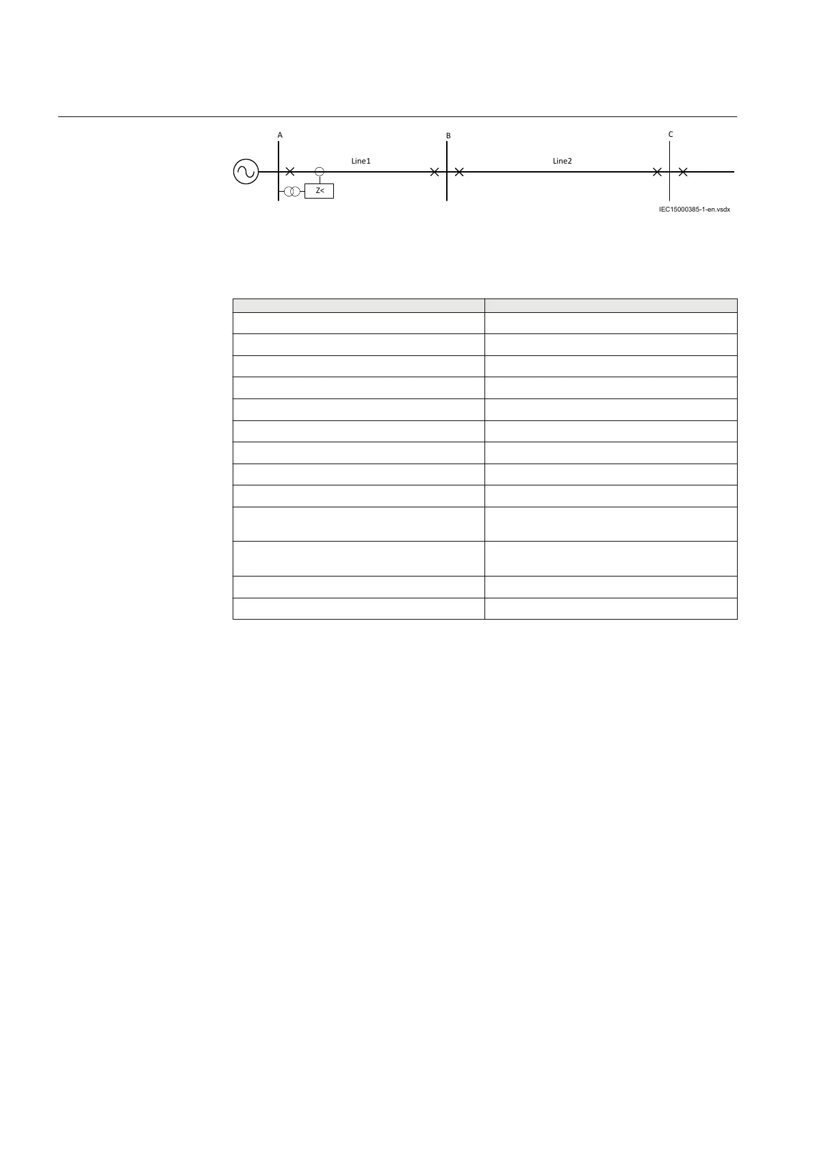
Figure 42: Considered single line diagram
Table 15: System Data
Parameter Value
System Voltage 110kV
System Frequency 16.7Hz
Full load 50MVA
Short time maximum Power 250% of Full load
Minimum operating voltage 90% of rated voltage
PT Ratio 110kV/110V
CT Ratio 600/1A
Line length A-B 50km
Line length B-C 100km
Positive sequence impedance of line 0.097 + j0.112 Ohm/km = 0.1481 ∟ 49.3°
Ohm/km
Zero sequence impedance of line 0.151 + j0.298 Ohm/km = 0.334 ∟ 63.13°
Ohm/km
Arc resistance 2 Ohm
Tower footing resistance 10 Ohm
General
GUID-0539986A-C449-4E29-9067-ACF82F94995C v2
Common base IED values for primary current (IBase) and primary voltage (UBase)
are set in a Global base values for settings function GBASVAL.
GlobalBaseSel: It is used to select a GBASV
AL function for reference of base
values.
IBase: Sets the base current in primary ampere. This is 50MVA/110kV = 454.54A.
UBase: Sets the base voltage in kV. This is 110.0kV.
Operation: Sets the protection to On/Off. Set this to On.
System Earthing: It is used to select the type of system earthing. Select the
Compensated.
LineAng: Set it to 50 deg.
IMinOpPE: It is used to select the minimum operating current for the phase-to-
earth loops. Set this to 10% IB.
Section 7 1MRK 506 375-UEN A
Impedance protection
136 Railway application RER670 2.2 IEC
Application manual