15.1.4.1 Setting examples
SEMOD54481-4 v5
Three setting examples, in connection to Measurement function (CVMMXN
), are
provided:
• Measurement function (CVMMXN) application for a OHL
• Measurement function (CVMMXN) application on the secondary side of a
transformer
For each of them detail explanation and final list of selected setting parameters
values will be provided.
Several instances of each type of measurement function blocks are
available in the IED. The actual reported values from the IED are
dependent on the logic configuration made in PCM600.
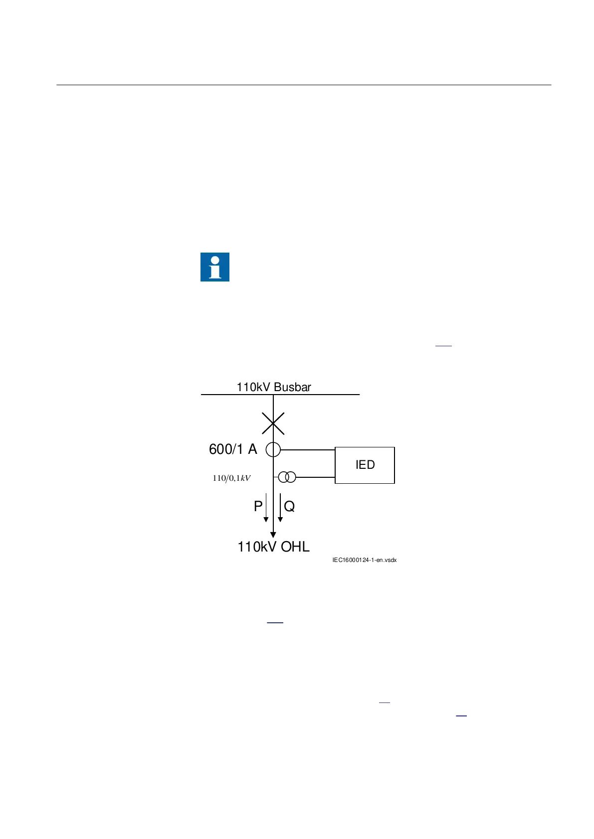
Measurement function application for a 110kV OHL
SEMOD54481-12 v11
Single line diagram for this application is given in figure 160:
110kV Busbar
110kV OHL
P Q
600/1 A
IEC16000124-1-en.vsdx
IED
IEC16000124 V1 EN-US
Figure 160: Single line diagram for 110kV OHL application
In order to monitor, supervise and calibrate the active and reactive power as
indicated in figure
160 it is necessary to do the following:
1. Set correctly CT and VT data and phase angle reference channel
PhaseAngleRef using PCM600 for analog input channels
2.
Connect, in PCM600, measurement function to two-phase CT and VT inputs
3. Set under General settings parameters for the Measurement function:
• general settings as shown in table
38.
• level supervision of active power as shown in table 39.
1MRK 506 375-UEN A Section 15
Monitoring
Railway application RER670 2.2 IEC 385
Application manual